Winding and time-setting control device for a timepiece movement

a control device and timepiece technology, applied in the direction of mechanical devices for setting time, mechanical time indication, instruments, etc., can solve the problems of frame necessarily occupying a certain volume, inconvenient and unattractive, inaccuracy of axial positions of first stems, etc., to achieve simple and more compact, easy to integrate

Active Publication Date: 2011-09-08
MONTRES BREGUET
View PDF11 Cites 9 Cited by
  • Summary
  • Abstract
  • Description
  • Claims
  • Application Information

AI Technical Summary

Benefits of technology

[0009]It is an object of the invention to create an improved device compared to the state of the art, in the sense that the device is much simpler and more compact, and is easy to integrate in an existing movement.
[0014]Thus, the switching between winding and time-setting via the axial movement of the first stem is carried out on the second stem by means of an improved pull-out mechanism, which is compact and particularly rigid, which avoids the aforementioned drawbacks of a frame that moves in translation. The pull-out device has the advantage of being proven and low in height. The position of the shifted intermediate pinion permits any desired distance of centres value between the control stem and the movement stem.
[0015]It is particularly easy to adapt the device to existing movements.
[0016]According to a preferred embodiment of the invention, the second stem does not slide and includes a section of non-circular transverse section, for example square section, on which the sliding pinion is slidably engaged, said pinion having a peripheral groove in which one end of a lever of the pull-out mechanism engages. This results in a very compact construction with simplified bearings.

Problems solved by technology

The external crown of a usual winding stem would then be considerably closer to the back cover of the case than the bezel, which would be both inconvenient and unattractive.
Further, the connection for securing the two stems in translation requires a movable frame containing the gear and increasing the space required by the device.
The axial play that inevitably exists in this frame leads to inaccuracies in the axial positions of the first stem, given that the axial position is generally indexed on the second stem.
However, the frame necessarily occupies a certain volume in the watch case.
Moreover, pivotal guiding is restricted, and the suspended coupling by the frame is not favourable for the passage of high torque during winding.
The axial play also leads to inaccuracy in the axial position of the stems.

Method used


Image

  • Winding and time-setting control device for a timepiece movement
  • Winding and time-setting control device for a timepiece movement
  • Winding and time-setting control device for a timepiece movement

Examples


Embodiment Construction

[0023]The invention concerns the field of winding and time-setting mechanisms for timepiece movements.

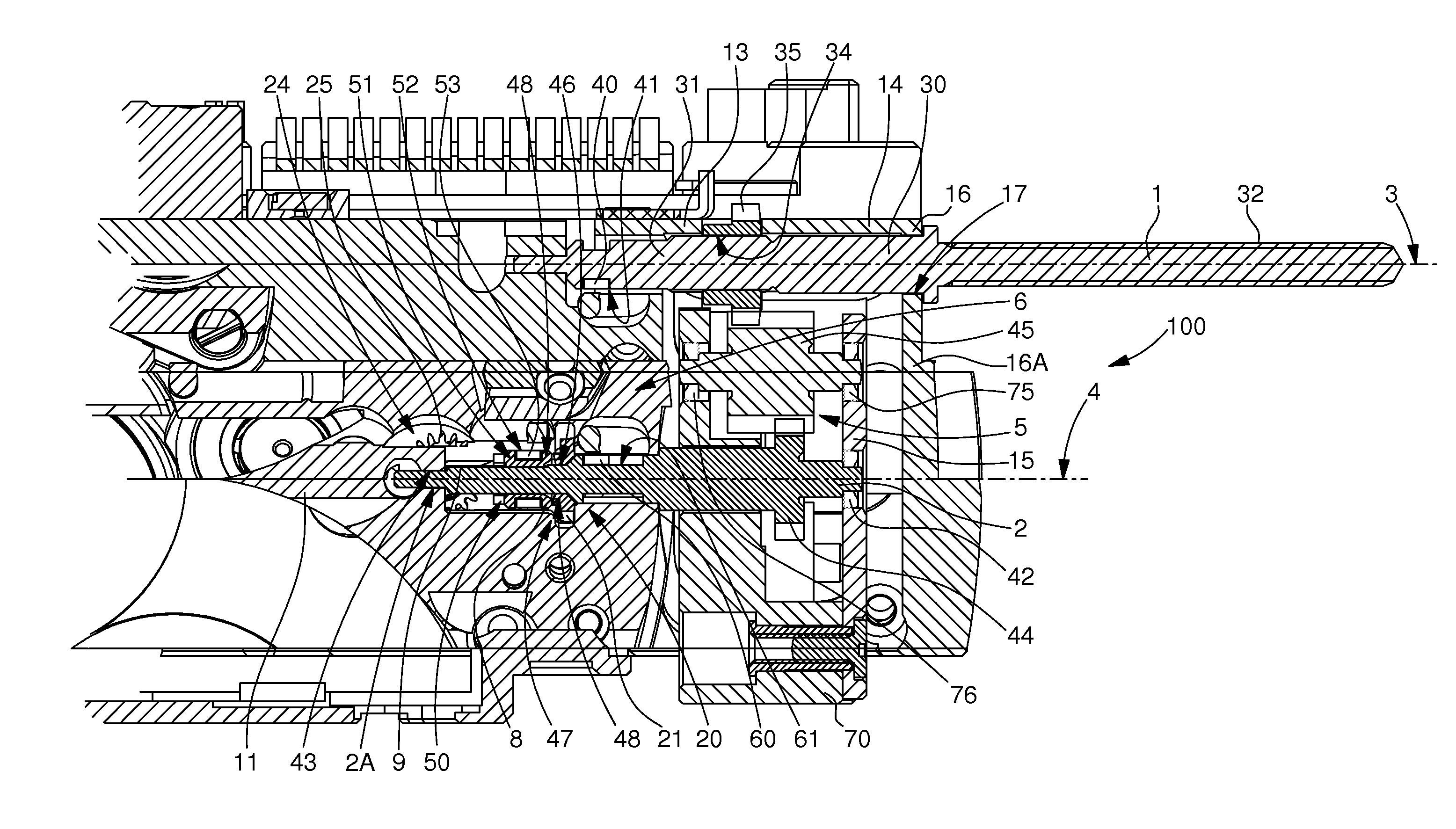
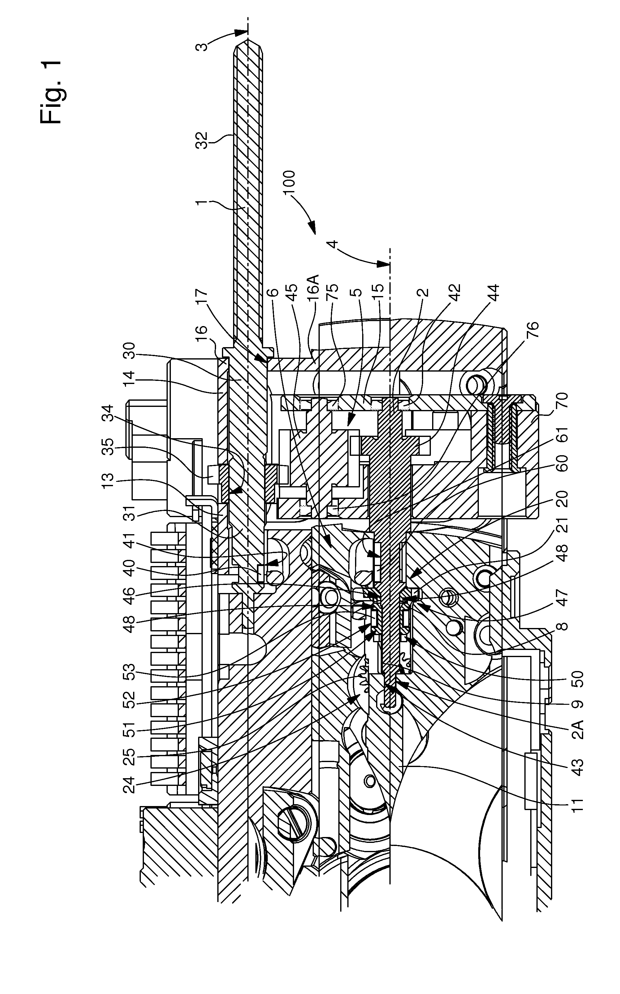
[0024]The invention concerns a winding and time-setting control device 100 for a timepiece movement.

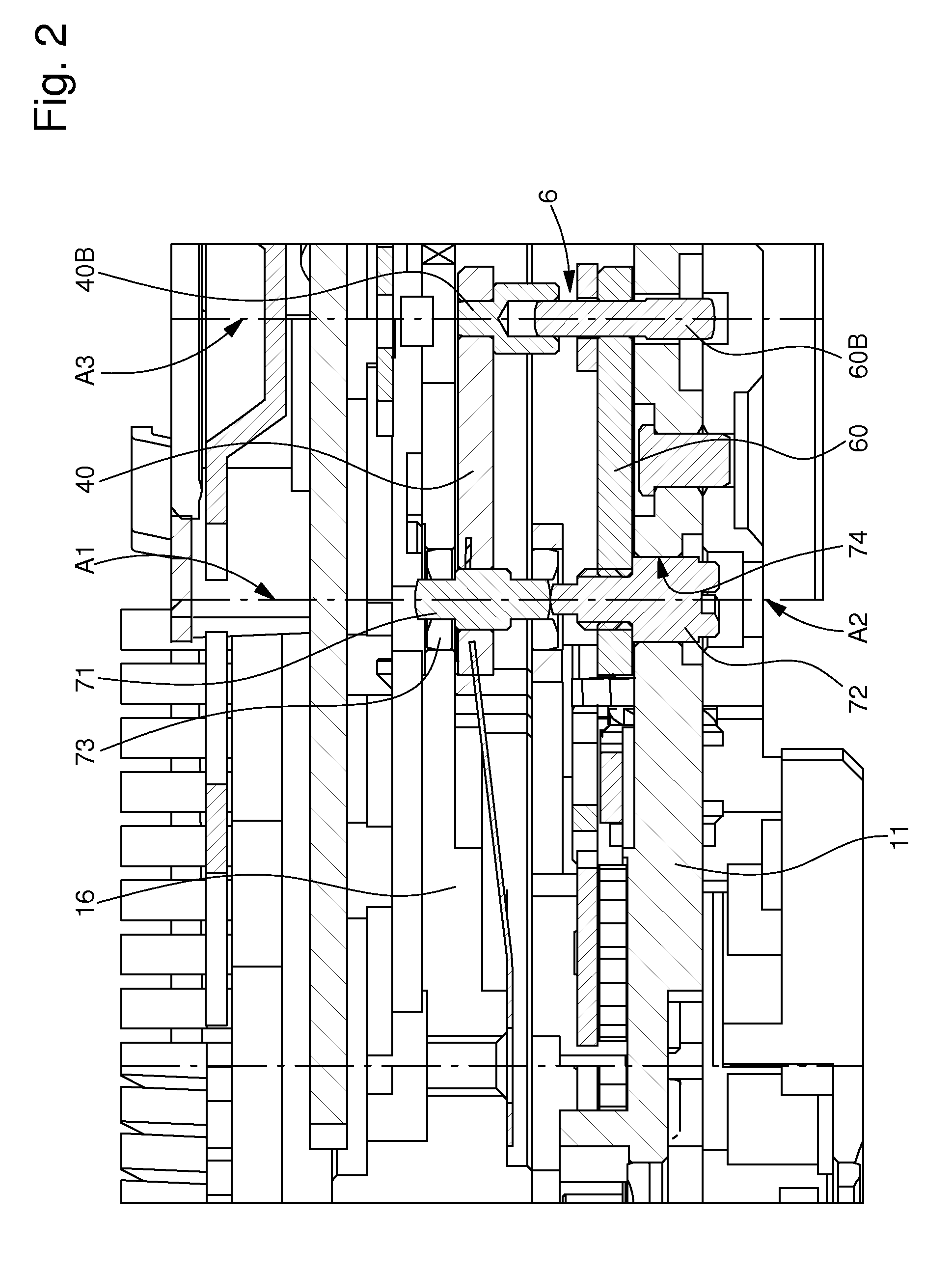
[0025]The device shown in the drawings includes two winding and time-setting stems, namely a control stem 1 and a movement stem 2, whose respective axes of rotation 3 and 4 are parallel, but shifted in height in relation to each other, in a perpendicular or oblique direction relative to the general plane of the timepiece movement. These stems 1 and 2 are connected by two kinematic links, namely a gear transmission 5, which is permanently meshed and transmits the rotation from one stem to another, and a pull-out mechanism 6, which transmits axial movements from first stem 1 to a sliding pinion 8. The entire device is supported, from a movement plate 1 of the timepiece, by fixed elements or bridges. A winding mechanism 20, whose winding pinion 21 can be seen in the drawings, and a time-...


PUM


Abstract

The invention concerns a winding and time-setting control device (100) for a timepiece movement including, connected in rotation, a movement stem (2) secured in rotation to a sliding pinion (8) driven in translation by a lever (52) between winding and time-setting positions, and a control stem (1) sliding between winding and time-setting control positions, actuating a pull-out mechanism (6). It is characterized in that the mechanism (6) includes a first pull-out piece (40) including, about a first axis (A1), an arm (40A) movable with the control stem (1), and a pivot (40B) cooperating with a complementary pivot (60B) of a second pull-out piece (60) driving the lever (52) and including an arm (60A) movable inside a housing (61) in the movement stem (2). The invention also concerns a timepiece incorporating a device (100) of this type.

Description

[0001]This application claims priority from European Patent Application No. 10155792.4 filed Mar. 8, 2010, the entire disclosure of which is incorporated herein by reference.FIELD OF THE INVENTION[0002]The invention concerns a winding and time-setting control device for a timepiece movement of the type including a movement stem that rotates about an axis in a movement plate and is secured in rotation to a sliding pinion. The pinion is axially movable under the action of a sliding pinion lever along said axis in translation between, on the one hand, a winding position in which said sliding pinion is arranged for cooperating with a winding mechanism to set the latter in rotation, and, on the other hand, a time-setting position in which said sliding pinion is arranged for cooperating with a time-setting mechanism to set the latter in rotation. Said device includes, connected in rotation to said movement stem by transmission means and shifted relative to said movement stem, a control st...

Claims


Application Information

Patent Timeline
Patent Type & Authority Applications(United States)
IPC IPC(8): G04B27/02
CPCG04B37/066G04B27/04
Inventor PITTET, JAN
Owner MONTRES BREGUET
Why Eureka
Try Eureka