Electrophoretic display fluid

a display fluid and electrophoretic technology, applied in the field of electrophoretic display fluid, can solve the problems of limited whiteness and limited whiteness displayed by the display device, and achieve the effect of increasing contras

Inactive Publication Date: 2011-09-08
SIPIX IMAGING INC
View PDF83 Cites 77 Cited by
  • Summary
  • Abstract
  • Description
  • Claims
  • Application Information

AI Technical Summary

Benefits of technology

[0015]The electrophoretic fluid of the present invention has many advan

Problems solved by technology

In the former case where white charged particles are dispersed in a dark colored solvent, the whiteness displayed by the display device is limited by absorption of light in the interstitial locations between the white charged particles and by the amount of white particles that can go into the flu

Method used


Image

  • Electrophoretic display fluid
  • Electrophoretic display fluid
  • Electrophoretic display fluid

Examples


Embodiment Construction

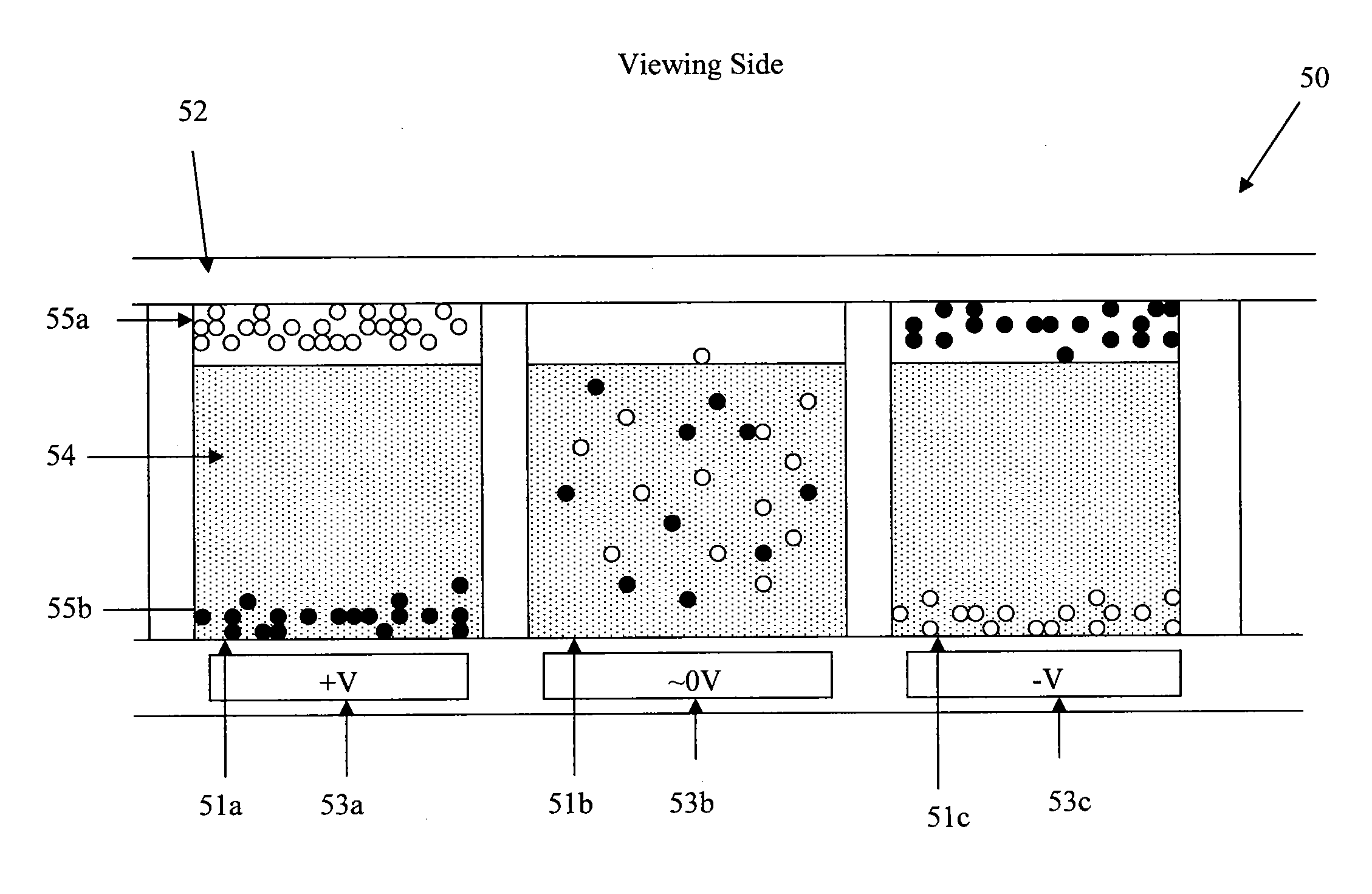
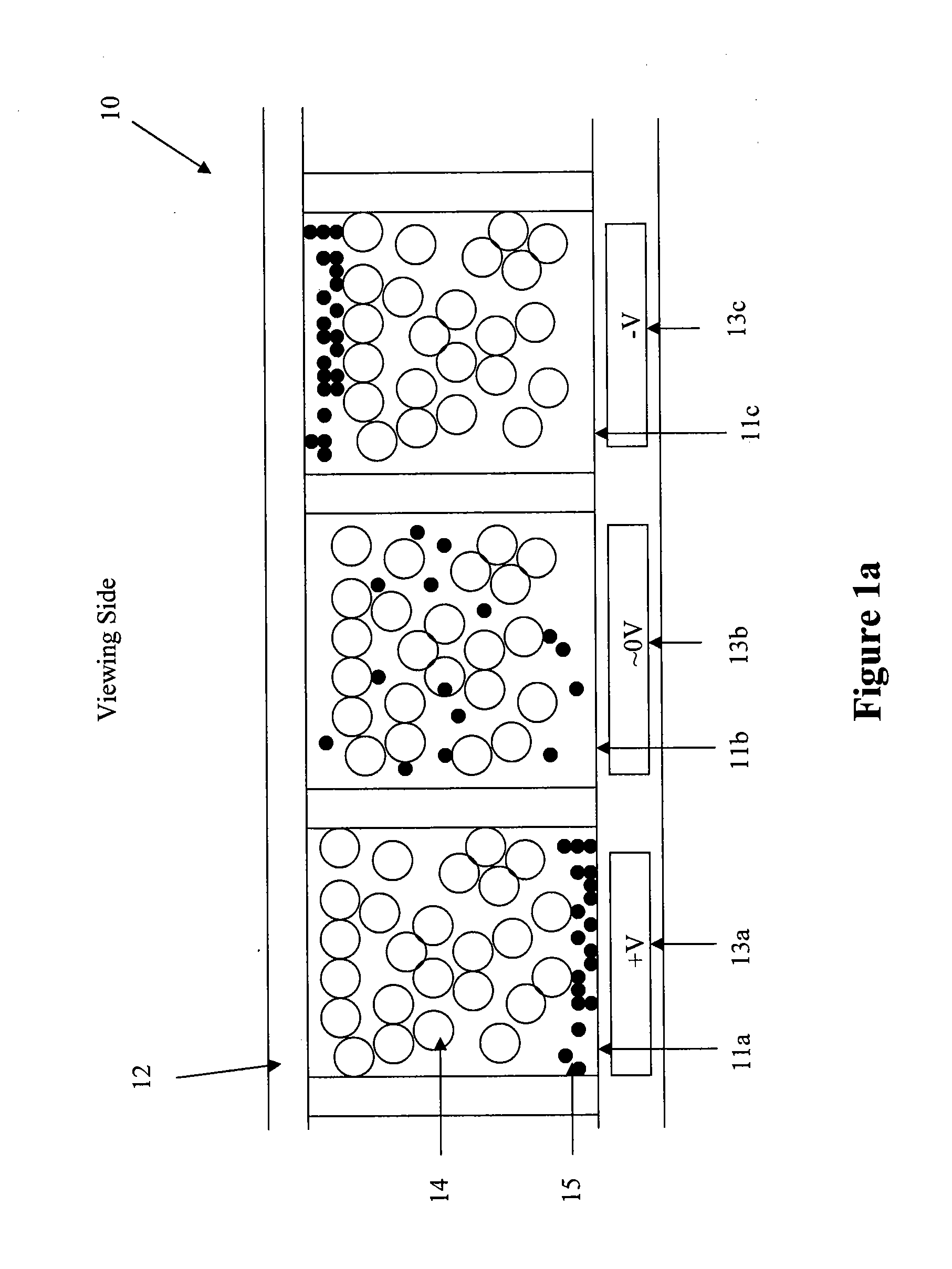
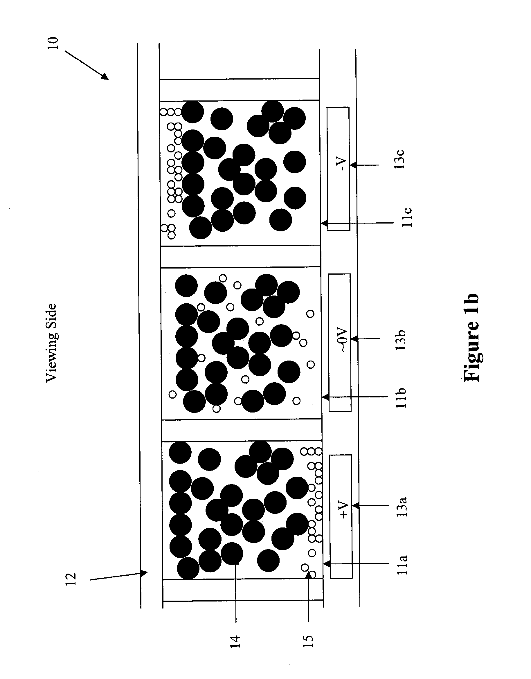
[0018]The present invention is directed to an electrophoretic fluid which comprises a non-mobile or semi-mobile phase and charged pigment particles.

[0019]The non-mobile or semi-mobile phase (e.g., particles or solid porous matrix) is, by definition, far less responsive to the applied electric field than the charged pigment particles. Indeed, the non-mobile or semi-mobile phase may even be fixed in location and not move at all. The key defining part of the non-mobile or semi-mobile phase is that with an applied electric field, the charged pigment particles move through the interstitial spaces in the phase so that the image changes because the charged pigment particles are either on top of the non-mobile or semi-mobile phase (to cause the viewer to see the color of the charged pigment particles) or at the bottom (to cause the viewer to see the color of the non-mobile or semi-mobile phase).

[0020]In the first aspect of the invention, the non-mobile or semi-mobile phase comprises non-mob...


PUM


Abstract

The present invention is directed to an electrophoretic fluid which comprises a non-mobile or semi-mobile phase and charged pigment particles. The fluid has many advantages, such as increased contrast without affecting the switching speed.

Description

[0001]This application claims the benefit of U.S. Provisional Application No. 61 / 309,796, filed Mar. 2, 2010, which is incorporated herein by reference in its entirety.FIELD OF THE INVENTION[0002]This invention relates to an electrophoretic display fluid comprising a non-mobile or semi-mobile phase and charged pigment particles, and an electrophoretic display device utilizing such a display fluid.DESCRIPTION OF RELATED ART[0003]The electrophoretic display (EPD) is a non-emissive device based on the electrophoresis phenomenon influencing charged pigment particles suspended in a colored dielectric solvent. An EPD typically comprises a pair of opposed, spaced-apart plate-like electrodes. At least one of the electrodes, typically on the viewing side, is transparent. An electrophoretic fluid composed of a colored dielectric solvent and charged pigment particles dispersed therein is enclosed between the two electrode plates. When a voltage difference is imposed between the two electrode p...

Claims


Application Information

Patent Timeline
IPC IPC(8): G03G17/04
CPCG03G17/04G02F2001/1678G02F1/167
Inventor SPRAGUE, ROBERT A.
Owner SIPIX IMAGING INC
Why Eureka
Try Eureka