Method for supporting analytical work of solder printing state and solder printing inspection machine

a technology of solder printing and analytical work, which is applied in the direction of soldering equipment, manufacturing tools, instruments, etc., can solve the problems of solder seeping outside the land, defect is easily generated, and quality degradation of printing regions, so as to facilitate the confirmation of a relationship, improve productivity, and improve the effect of productivity

Inactive Publication Date: 2011-09-08
ORMON CORP
View PDF4 Cites 18 Cited by
  • Summary
  • Abstract
  • Description
  • Claims
  • Application Information

AI Technical Summary

Benefits of technology

[0029]In the above solder printing inspection machine, the user can confirm the quality of the reintroduced board and the quality of the board subsequent to the reintroduced board from the graph displayed on the monitor while performing the inspection.
[0030]In one or more embodiments of the solder printing inspection machine, when the display target graph includes the quality data of the board corresponding to the inspection result data bundled with the identification code identical to that of the reintroduced board, the information display unit explicitly shows the data as a quality data corresponding to the board extracted from the production line in a mode different from the quality data corresponding to the reintroduced board. In the display of the information display unit, when the defect is generated in the reintroduced board or the board subsequent to the reintroduced board to extract the defective board,

Problems solved by technology

However, sometimes quality of printing region is degraded due to mask exchange or mask clogging in a solder printer and a fluctuation in supply of the cream solder.
In the actual operation, it is found that sometimes the defect is easily generated by reintroducing the board.
For example, when the extracted board is insufficiently washed, sometimes the ne

Method used


Image

  • Method for supporting analytical work of solder printing state and solder printing inspection machine
  • Method for supporting analytical work of solder printing state and solder printing inspection machine
  • Method for supporting analytical work of solder printing state and solder printing inspection machine

Examples


Embodiment Construction

[0050]In embodiments of the invention, numerous specific details are set forth in order to provide a more thorough understanding of the invention. However, it will be apparent to one with ordinary skill in the art that the invention may be practiced without these specific details. In other instances, well-known features have not been described in detail to avoid obscuring the invention.

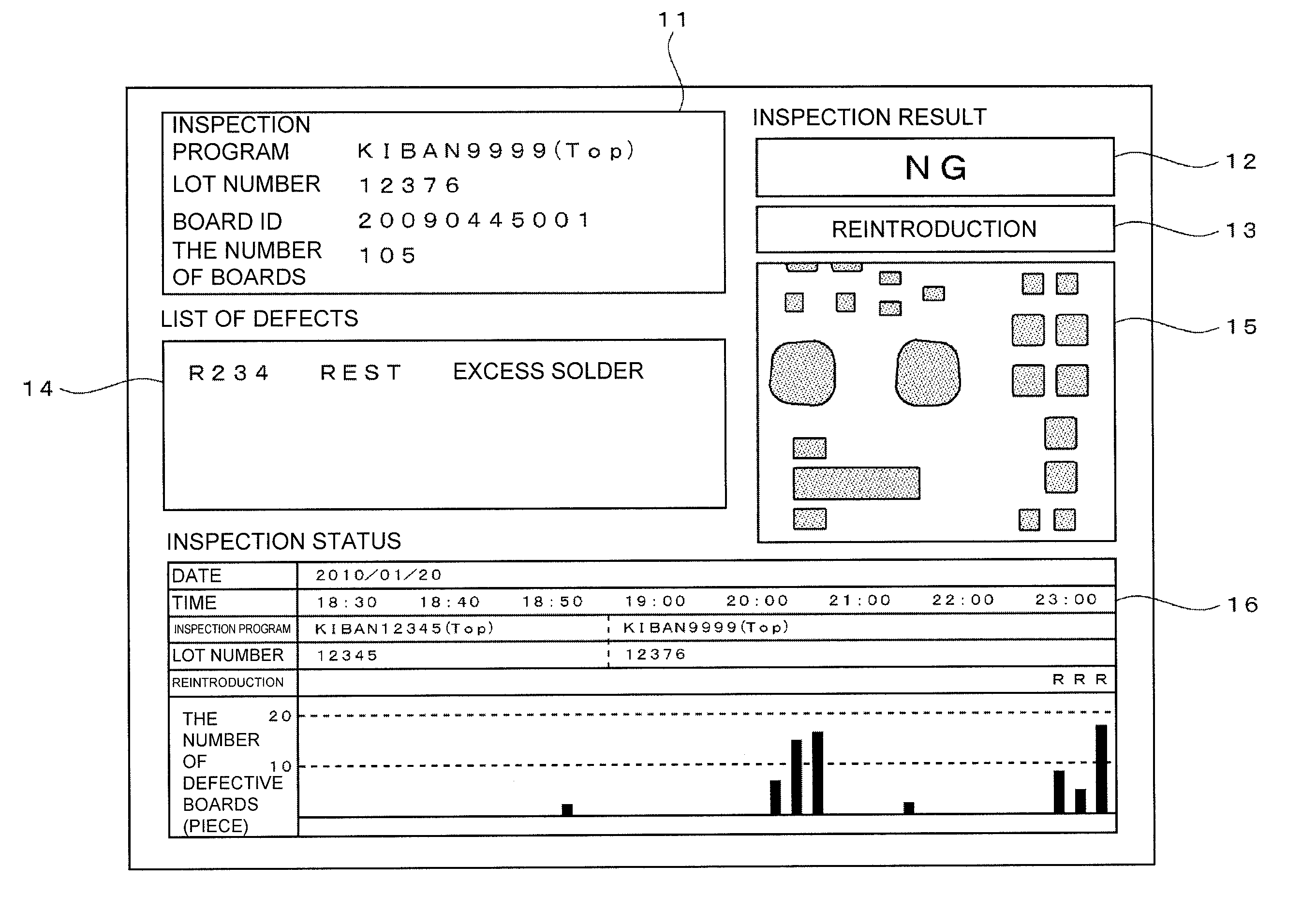
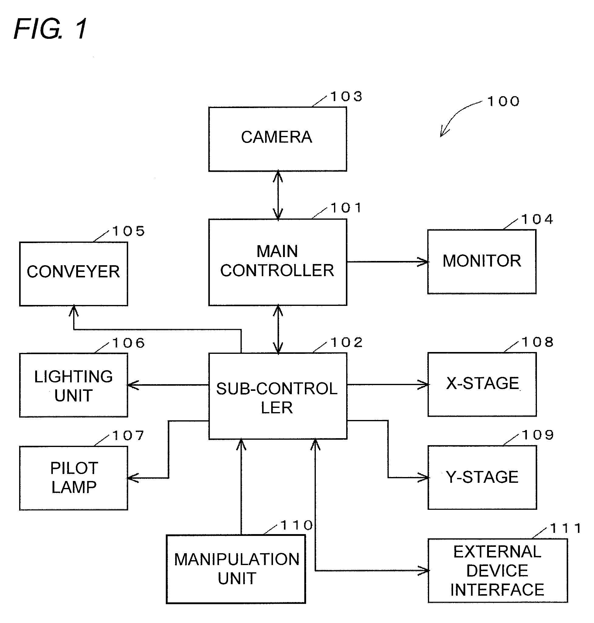
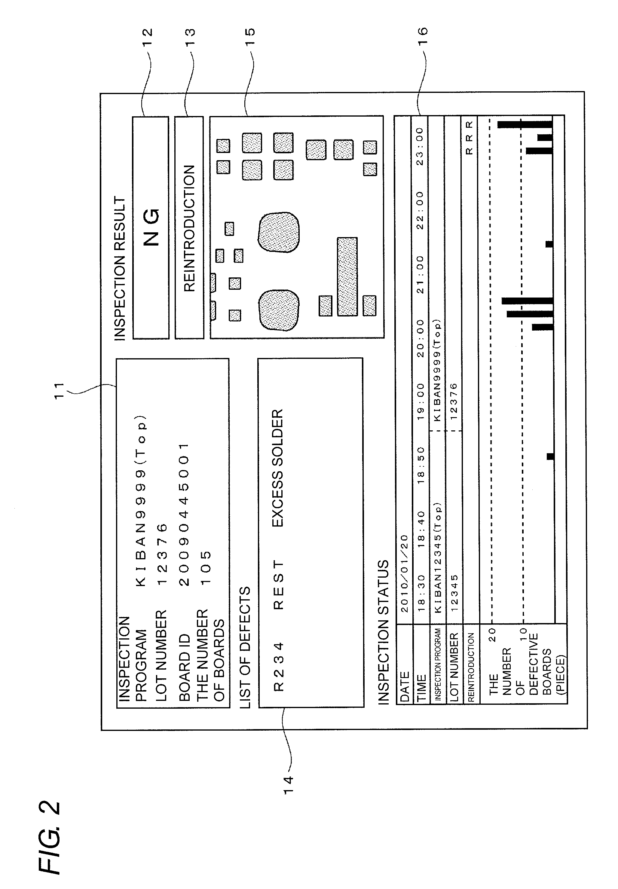
[0051]FIG. 1 is a block diagram illustrating a configuration of a solder printing inspection machine 100. The solder printing inspection machine 100 is installed in a solder printing process of a component mounting board production line to inspect whether or not an amount of solder printed in an electrode (land) on a board side or a printing range of the solder is proper. In FIG. 1, a main controller 101 and a sub-controller 102 are computers including CPUs and memories. The main controller 101 includes a communication interface that conducts network communication. The main controller 101 is connected...


PUM

PropertyMeasurementUnit
Timeaaaaaaaaaa

Abstract

In a solder printing inspection machine, an identification code and an inspection time of an inspection target board are accumulated in a memory. The accumulated data, whose identification code is matched with that of the current inspection target board, is searched while the accumulated data is traced back one by one. When the corresponding board is found, it is recognized that the board is extracted because of the defective board and the inspection target board is the reintroduced board that was previously extracted. A graph, in which pieces of information expressing the pieces of quality of the boards are arrayed in time series, is produced based on each time of inspection result and the graph is displayed on a monitor. In the pieces of data included in the graph, the data corresponding to the board that is recognized as the reintroduction is explicitly shown by a letter “R”.

Description

BACKGROUND OF THE INVENTION[0001]1. Technical Field[0002]One or more embodiments of the present invention relate to a method for inspecting a solder printing state of a board in which cream solder is printed before a component is mounted and supporting analytical work of the solder printing state based on the inspection result, and a solder printing inspection machine in which the method is adopted.[0003]2. Related Art[0004]In a solder printing process that is a first process on a component mounting board production line, it is necessary to transfer a proper amount of solder to many electrodes (lands) on the board. However, sometimes quality of printing region is degraded due to mask exchange or mask clogging in a solder printer and a fluctuation in supply of the cream solder.[0005]In order to possibly lessen degradation, it has been proposed that a graph in which an amount of solder on the board is inspected after the solder printing and the amount of solder measured in each inspec...

Claims


Application Information

Patent Timeline
IPC IPC(8): G06F19/00
CPCG01B11/00G01B11/06G01B11/28H05K13/08H05K2203/163H05K3/225H05K3/1216H05K13/083B23K1/00G01B11/24G06T7/00H05K3/34
Inventor MORI, HIROYUKI
Owner ORMON CORP
Why Eureka
Try Eureka