
Servo system, servo motor driving device, safety unit and method for controlling servo system

a technology of servo motor and driving device, which is applied in the direction of electric programme control, program control, instruments, etc., can solve the problems of common failures of these encoders, increased system cost, and additional time and cost for initial setting of encoders, so as to ensure the safety of the servo system

Active Publication Date: 2011-09-15
ORMON CORP
View PDF5 Cites 27 Cited by
  • Summary
  • Abstract
  • Description
  • Claims
  • Application Information

AI Technical Summary

Benefits of technology

[0017]A non-limiting feature of the disclosure is to assure safety of a servo system without replacing the encoder used in the servo system with an encoder having a safety function.
[0034]Accordingly, the safety of the servo system can be assured without replacing the encoder used in the servo system with an encoder having a safety function.

Problems solved by technology

Recently, along with reducing costs and improving productivity, taking measures to assure safety for workers has become an important issue in the manufacturing scenes.
In addition, the cost of the system increases as the number of encoders increases.
However, additional time and costs for the initial settings of the encoders are necessary.
Also, when the two encoders have the same circuitry, common failures may occur in these encoders.
Also, if an encoder is used in which two mutually independent positional data sets are generated, such as the encoder of the SIN / COS type, or if two mutually independent encoders are used as described above, feedback control with the use of two data sets may be complicated.
In addition, since the circuitry is configured to generate two data sets with one encoder, the cost for the encoder may increase.
When the transmission distance of an analog signal is long, the signal tends to attenuate or be affected by noise, and thus the reliability of the detection value decreases.

Method used


Image

  • Servo system, servo motor driving device, safety unit and method for controlling servo system
  • Servo system, servo motor driving device, safety unit and method for controlling servo system
  • Servo system, servo motor driving device, safety unit and method for controlling servo system

Examples


Embodiment Construction

[0043]Hereinafter, preferred embodiments of the disclosure will be described in detail with reference to the drawings. In the drawings, identical or equivalent components are designated by identical numerals, and the overlapping description is omitted.

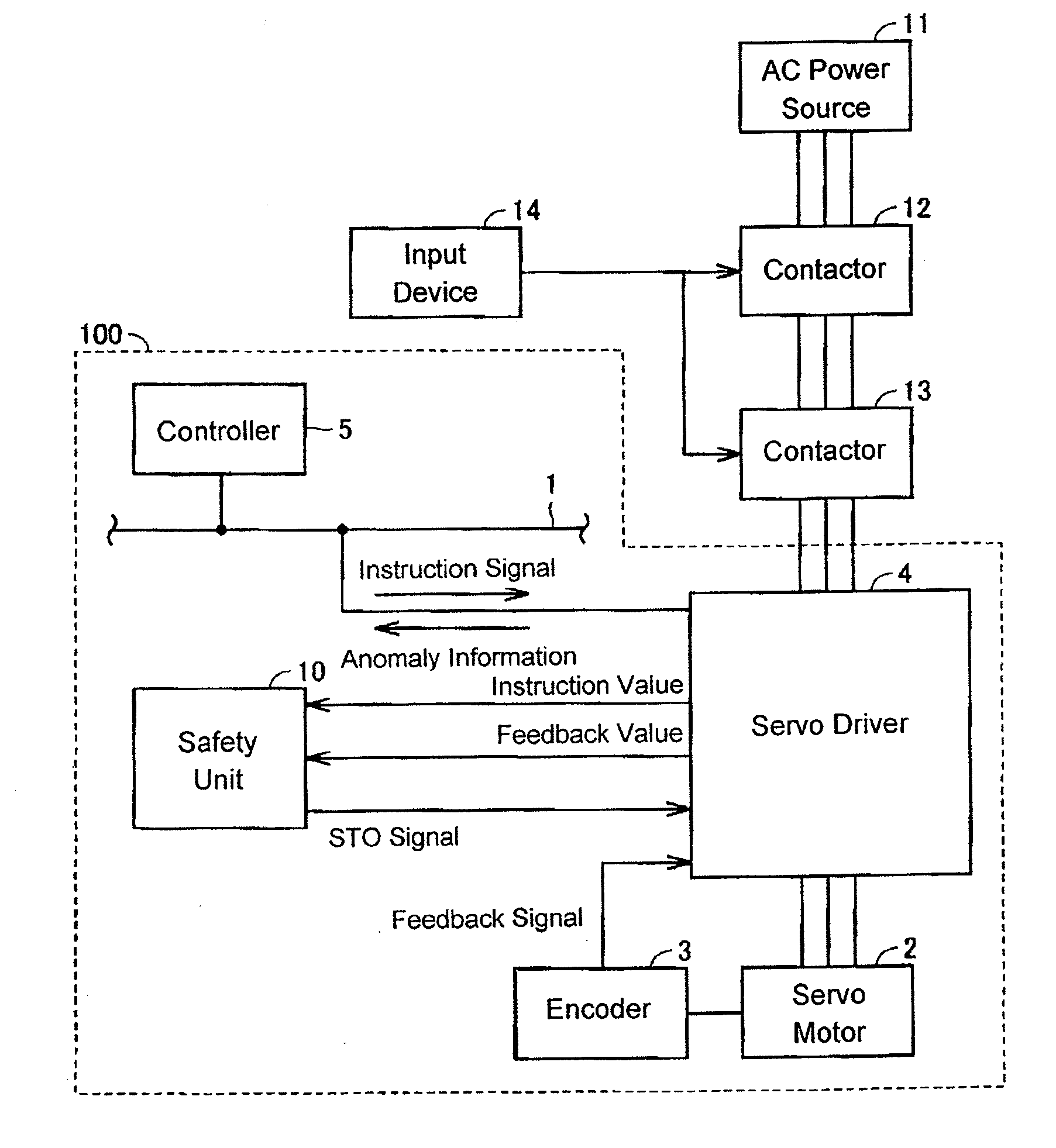
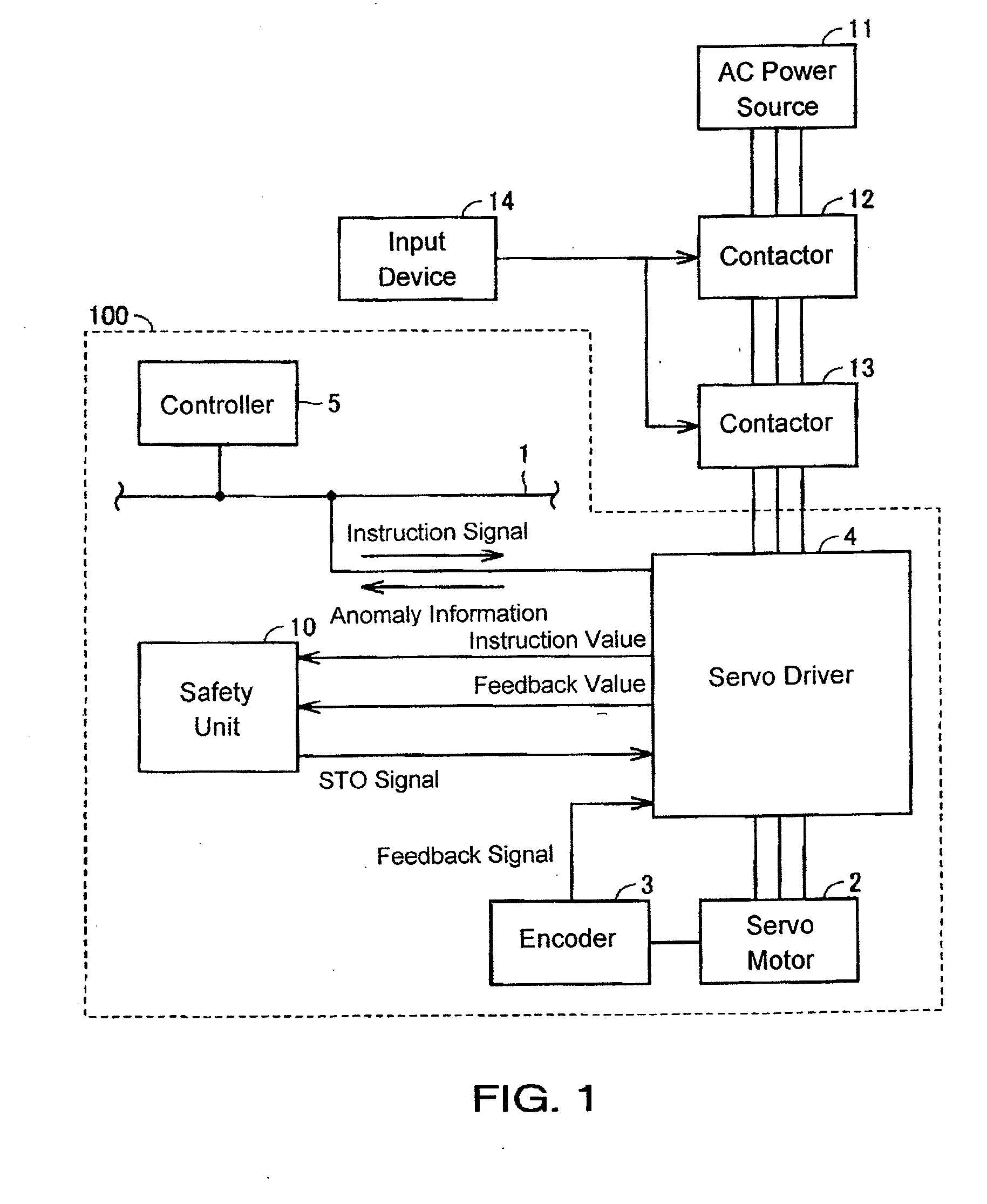
[0044]FIG. 1 is a schematic configuration diagram illustrating a servo system according to an embodiment of the disclosure. Referring to FIG. 1, a servo system 100 is used as a system for driving various types of mechanical equipment not shown in the drawings (e.g., arms of industrial robots). The servo system 100 includes a network 1, a servo motor 2, an encoder 3, a servo driver 4, a controller 5 and a safety unit 10.

[0045]The servo motor 2 is an AC servo motor, for example. The encoder 3 is attached to the servo motor 2 in order to detect an operation of the servo motor 2. The encoder 3 generates a feedback signal representing the detected operation of the servo motor 2, and sends the feedback signal to the servo driver 4. The feedb...


PUM


Abstract

A servo driver sets an instruction value for an operation of a servo motor based on an instruction signal from a controller. The servo driver sends the instruction value and a feedback value obtained based on a feedback signal to a safety unit. When at least one of the instruction value and the feedback value sent by the servo driver has an abnormal value, an STO signal is generated and sent to the servo driver. When the STO signal is input to the servo driver, the servo driver stops the supply of electricity to the servo motor.

Description

CROSS-REFERENCE TO RELATED APPLICATION[0001]This application claims benefit of priority under 35 U.S.C. §119 to Japanese Patent Application No. P2010-057465 filed on Mar. 15, 2010, which is expressly incorporated herein by reference in its entirety.BACKGROUND[0002]1. Field of the Disclosure[0003]The present disclosure relates to a servo system, a servo motor driving device, a safety unit and a method for controlling a servo system.[0004]2. Background Information[0005]Servo systems are used for positioning control of movable portions of various machines, for example. An example of such a servo system includes a servo motor for operating various types of mechanical equipment, an encoder attached to the servo motor, a servo driver for driving the servo motor, and a control device for outputting position instruction information or the like to the servo driver.[0006]Recently, along with reducing costs and improving productivity, taking measures to assure safety for workers has become an ...

Claims


Application Information

Patent Timeline
Patent Type & Authority Applications(United States)
IPC IPC(8): G05B23/02G05B9/02H02P29/00
CPCG05B19/4062G05B2219/42306G05B2219/33221G05B19/18G05B9/02
Inventor UENO, JUNICHI
Owner ORMON CORP
Learn More