
System and method for charging an energy storage system for an electric or hybrid-electric vehicle

a technology of energy storage system and electric or hybrid electric vehicle, which is applied in the direction of charging stations, hybrid vehicles, transportation and packaging, etc., can solve the problems of reducing charging performance, affecting charging efficiency, and affecting charging efficiency,

Inactive Publication Date: 2011-09-15
GENERAL ELECTRIC CO
View PDF29 Cites 152 Cited by
  • Summary
  • Abstract
  • Description
  • Claims
  • Application Information

AI Technical Summary

Problems solved by technology

However, this charging technique may be quite time consuming and may, for example, require up to 12 hours to fully charge the energy storage device.
Furthermore, the conductive engagement between the energy storage device and the electrical outlet tends to limit the location of charging stations, as environmental conditions such as rain, snow, and fog, etc. may reduce charging performance.
Thus, to initiate a charging cycle, the user must exit the vehicle, thereby becoming exposed to the environmental conditions.

Method used


Image

  • System and method for charging an energy storage system for an electric or hybrid-electric vehicle
  • System and method for charging an energy storage system for an electric or hybrid-electric vehicle
  • System and method for charging an energy storage system for an electric or hybrid-electric vehicle

Examples


Embodiment Construction

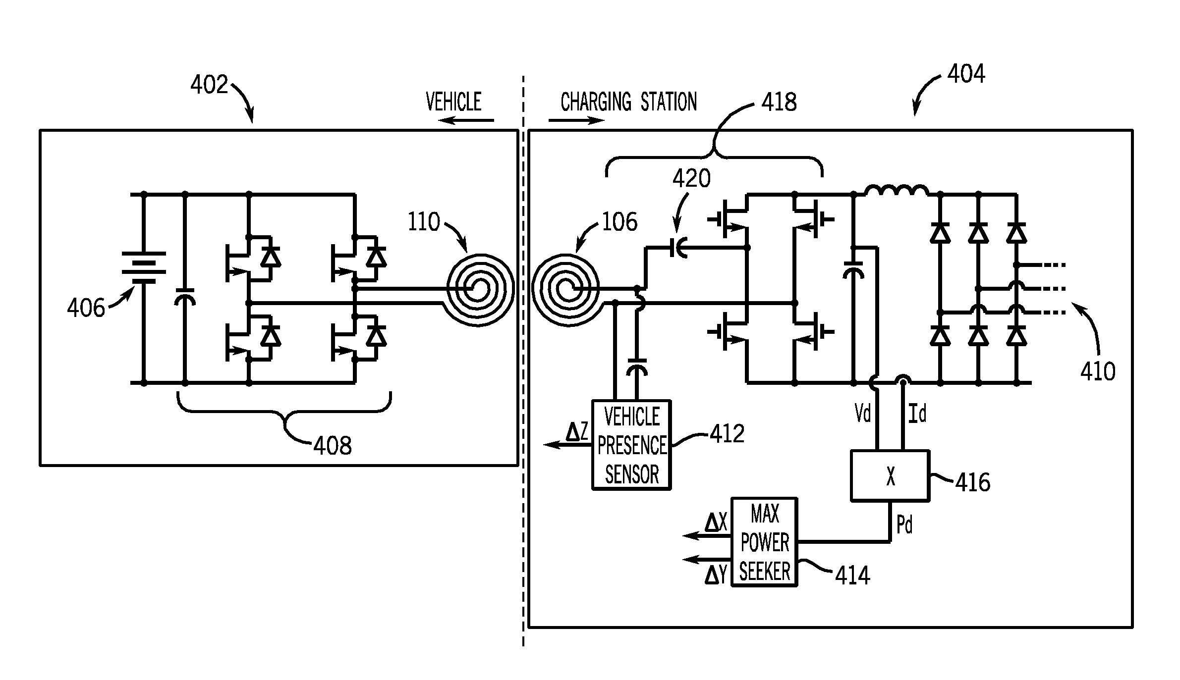
[0018]A system and method for electrical energy charging of an energy storage device for a vehicle or other device is shown, wherein the energy storage device is coupled to an energy charging assembly without the need for manual user application or interference.

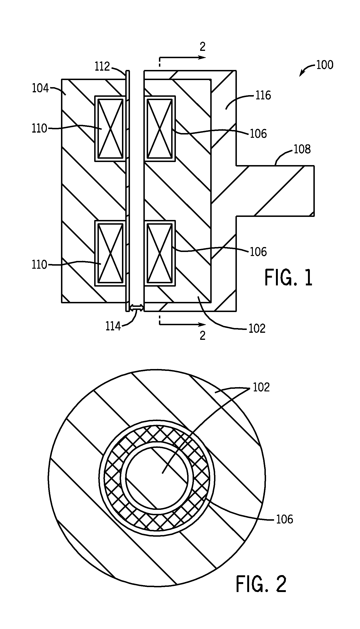
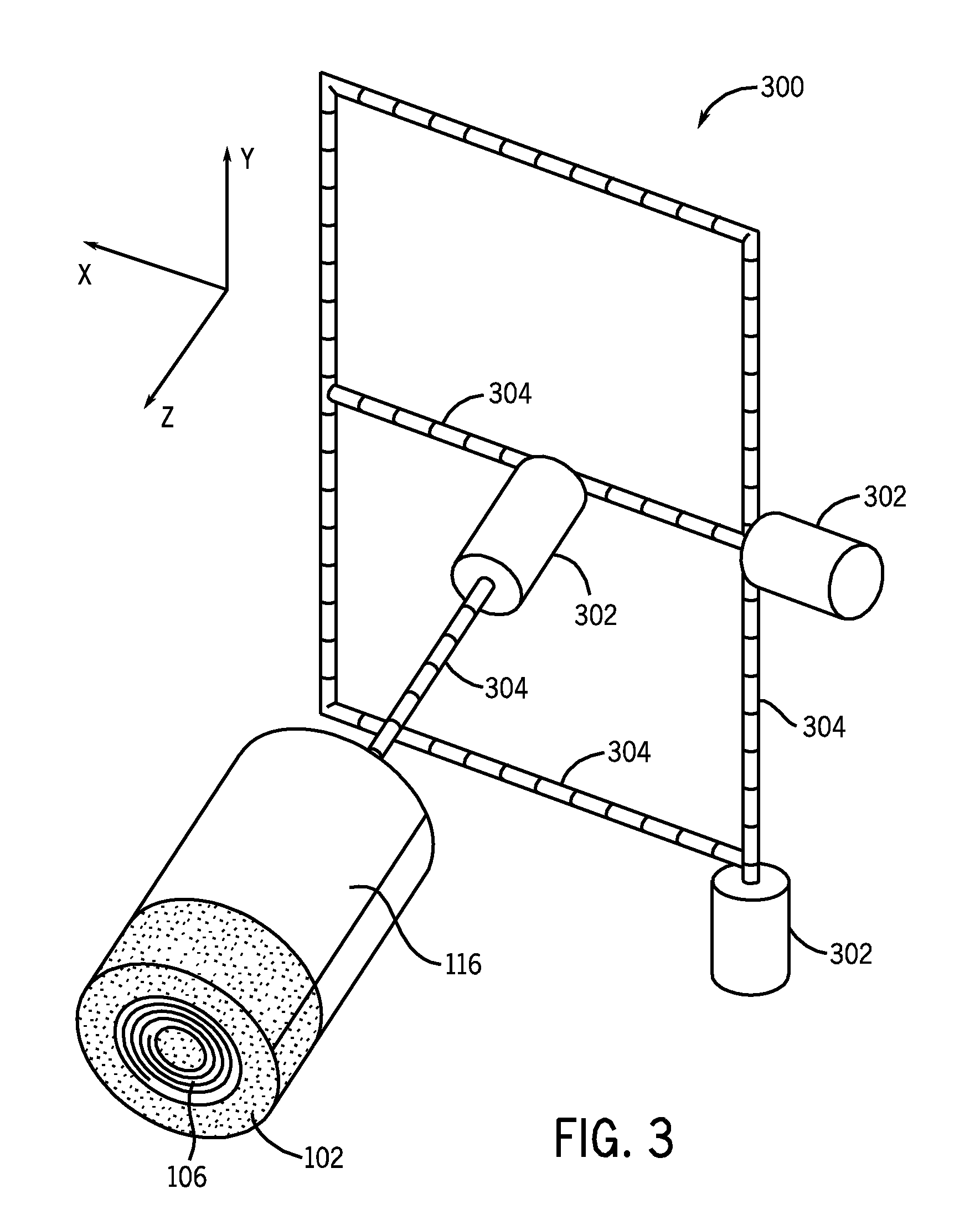
[0019]Referring to FIG. 1, a cross-sectional view of a contactor-less charging interface 100 in accordance with an embodiment of the invention is shown. Charging interface 100 comprises two magnetic cores 102, 104. Magnetic cores 102, 104 are preferably “pot core”-type structures, but other magnetic core structures may also be suitable. Magnetic core 102 comprises a charging coil 106 disposed therein, while magnetic core 104 comprises a charging coil 110 disposed therein. FIG. 2 illustrates a front view of magnetic core 102 or magnetic core 104 and respective charging coil 106, 110 along line 2-2. As can be seen in FIG. 2, charging coil 106, 110 encompasses a portion of magnetic core 102, 104 and is also surrounded by a porti...


PUM


Abstract

A system and method for electrical charging is disclosed. The electrical charging system comprises a first charging coil and an energy storage device coupled to the first charging coil. The energy charging system further comprises an energy charging station comprising a second charging coil disposed on a movable positioner, wherein the second charging coil is coupleable to an electrical energy source, at least one drive mechanism configured to translate the movable positioned, and a system controller. The system controller is configured to detect an event indicative of a proximity of the first charging coil to the energy charging station, translate the movable positioner such that the second charging coil is substantially aligned with, and closely spaced apart from, the first charging coil to form an electrical transformer, and initiate a charging cycle configured to transfer electrical energy to the at least one energy storage device via the electrical transformer.

Description

BACKGROUND[0001]Embodiments of the invention relate generally to an electrical charging system and, more particularly, to a system and method for charging an energy storage system of electric or hybrid-electric vehicle.[0002]Electric vehicles and hybrid-electric vehicles are typically powered by one or more energy storage devices, either alone or in combination with an internal combustion engine. In pure electric vehicles, the one or more energy storage devices power the entire drive system, thereby eliminating the need for an internal combustion engine. Hybrid-electric vehicles, on the other hand, include energy storage device power to supplement power supplied by an internal combustion engine, which greatly increases the fuel efficiency of the internal combustion engine and of the vehicle.[0003]Traditionally, the energy storage device in an electric or hybrid-electric vehicle included at least one battery capable of being charged via 120 V or 240 V power from a conventional electr...

Claims


Application Information

Patent Timeline
IPC IPC(8): H02J7/00
CPCB60L11/182H02J7/025Y02T10/7005Y02T90/122Y02T90/121B60L11/1829Y02T90/125Y02T90/12Y02T90/14B60L53/12B60L53/36B60L53/38H02J7/02Y02T10/7072B60L53/60B60L53/126H02J50/10H02J50/80H02J50/90H02J7/00034Y02T10/70H02J50/12
Inventor STEIGERWALD, ROBERT LOUISHERSHEY, JOHN ERIKHARTMAN, MICHAEL JAMESKING, ROBERT DEAN
Owner GENERAL ELECTRIC CO
Learn More