Device, method and computer readable medium for evaluating shape of optical element

a technology of optical elements and computer readable media, applied in image analysis, instruments, computing, etc., can solve the problems of reducing the accuracy of measurement, difficult for workers to read the deviation amount, and affecting the accuracy of measuremen

Inactive Publication Date: 2011-09-15
HOYA CORP
View PDF1 Cites 7 Cited by
  • Summary
  • Abstract
  • Description
  • Claims
  • Application Information

AI Technical Summary

Benefits of technology

[0008]The present invention is advantageous in that it provides a method, a device and a computer readable medium capable of quantitatively and suitably evaluating a processing error of a surface of an optical element to be inspected.

Problems solved by technology

However, since as shown in FIG. 9 the interference fringe has a wavy pattern, it is difficult for the worker to read the deviating amount.
Furthermore, since the rotationally symmetric wavefront irregularity is the deviating amount with respect to the above described approximation shape, the rotationally symmetric wavefront irregularity does not precisely represent the processing error of an actual product.
However, there is a problem that such a visual measurement involves a considerable amount of error.
Furthermore, there is a problem that, when the interference fringe is to be adjusted, the error fluctuates depending on a degree of adjustment, and therefore the accuracy of the measurement decreases.
There is also a problem that, when the deviation shape includes a rotationally asymmetric component, the degree of a curve of the interference fringe with respect to the adjustment varies depending on the rotationally asymmetric component, and thereby the measurement accuracy decreases.
Therefore, it is difficult to secure a high degree of reliability in the visual measurement.

Method used


Image

  • Device, method and computer readable medium for evaluating shape of optical element
  • Device, method and computer readable medium for evaluating shape of optical element
  • Device, method and computer readable medium for evaluating shape of optical element

Examples


Embodiment Construction

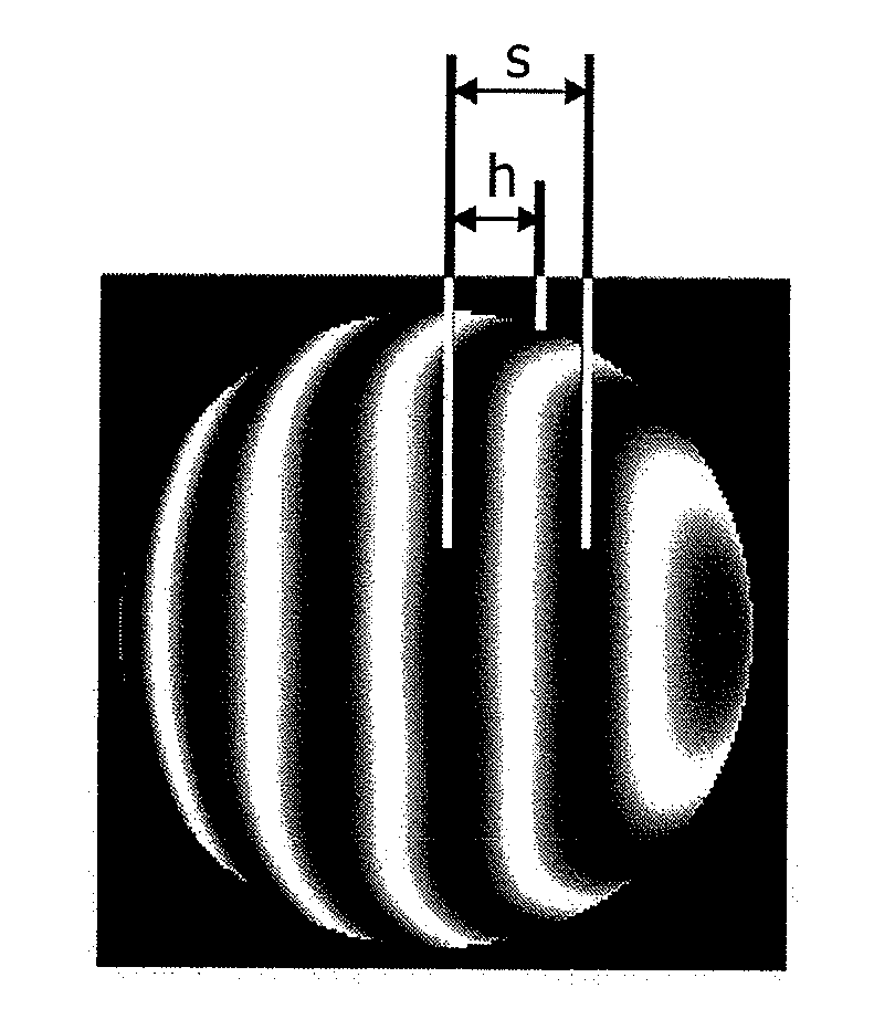
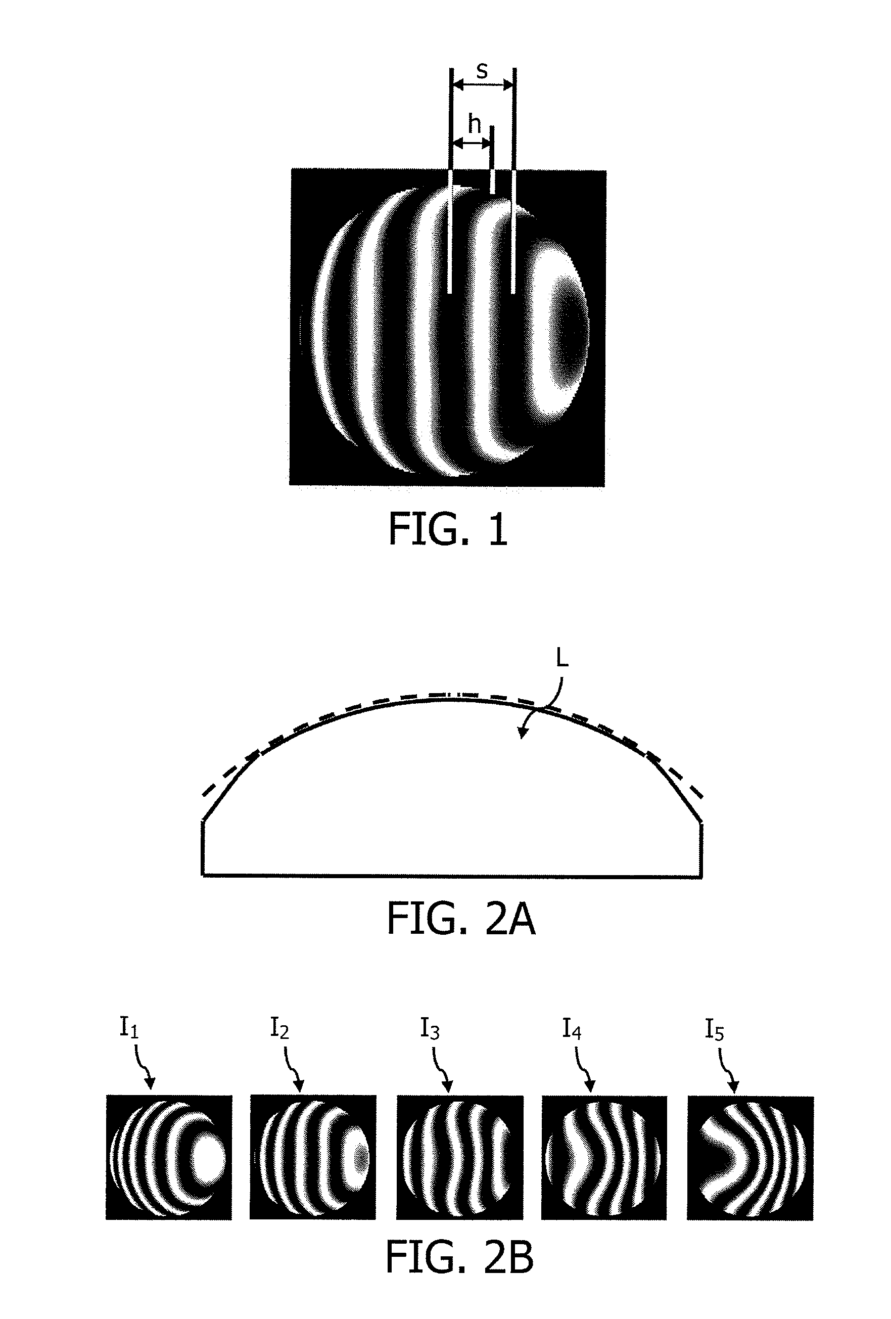
[0039]Hereinafter, an embodiment according to the invention is described with reference to the accompanying drawings. An actual product is produced such that a shape has a deviating amount falls within a tolerance with respect to an ideal shape. That is, a shape of an actual product (hereafter, referred to as an “actual product shape”) does not exactly coincide with the ideal shape. However, in this embodiment, the shape falling within the tolerance is regarded to be equivalent to the ideal shape not having a processing error. Since a testing surface of an optical element to be observed is processed with a high degree of precision, almost all of the entire region of the testing surface including an area around an optical axis is regarded as falling within the tolerance. Under such a premise, in this embodiment, the deviating amount with respect to a paraxial spherical surface of the actual product shape is measured and is subjected to image analysis so as to quantitatively evaluate ...


PUM


Abstract

A method for evaluating a shape of an optical element, including: executing polynomial approximation to obtain a deviation shape of a testing surface of an optical element with respect to an ideal surface; calculating an evaluation shape by extracting a rotationally symmetric irregularity component of the deviation shape from a result of the polynomial approximation; adding a 2nd order component to the evaluation shape so that a region including a pupil center of the evaluation shape is planarized; and calculating a rotationally symmetric irregularity value of the testing surface based on the evaluation shape to which the 2nd order component has been added.

Description

BACKGROUND OF THE INVENTION[0001]The present invention relates to a method, a device and a computer readable medium for evaluating a surface of an optical element, and more specifically to a method, a device and a computer readable medium for quantitatively evaluating a processing error of a surface shape of an optical element by image analysis.[0002]During a testing process of optical elements, evaluation values concerning the optical performance, such as a shape and the amount of aberration, are measured. For example, Japanese Patent Provisional Publication No. 2005-241592A (hereafter, referred to as JP2005-241592A) discloses an interference fringe analyzing device which obtains the amount of aberration from an interference fringe image. Specifically, the interference fringe analyzing device disclosed in JP2005-241592A is configured to simultaneously display an original image and an interference fringe image reconfigured with the amount of aberration obtained by analyzing the orig...

Claims


Application Information

Patent Timeline
Patent Type & Authority Applications(United States)
IPC IPC(8): G06K9/00
CPCG06T7/0057G06K9/525G06T7/521G06V10/435
Inventor KIMURA, SHINJI
Owner HOYA CORP
Why Eureka
Try Eureka