Hip replacement process

a hip replacement and process technology, applied in the field of human hip replacement, can solve the problems of inability to fully rotate the hip, and inability to move the hip, and achieve the effect of accurate ball pivoting

Inactive Publication Date: 2011-09-15
CAILLOUETTE JAMES THOMPSON +1
View PDF9 Cites 23 Cited by
  • Summary
  • Abstract
  • Description
  • Claims
  • Application Information

AI Technical Summary

Benefits of technology

[0012]c) fitting said ball in a socket on a hip bone, to pivot in the socket, said selection of base and neck, and tongue and groove connection between the size selected base and stem, enabling accurate pivoting of the ball.
[0013]The non-circular interfit is typically defined by at least one oval cross section of the tongue and groove, at the interfit location, as further may be defined by multiple oval lobes. This allows adjustment of the tongue and groove connection after the stem is fully inserted into the elongated recess in the femur. As will be seen, a block configuration of the base fitting in a pocket having tapered side flanges, and bottom and end walls, secures the base in position, and allows for securement of a range of different length bases, with selected neck positioning.

Problems solved by technology

These components must be accurately relatively positioned to accommodate to each patient's particular femur and hip socket configuration, as during surgery, which is time consuming and subject to adjustment problems and difficulties.
It is found that the stem may not seat at a local predicted by the surgery, and that dislocation may occur resulting from use of decreased offset (lateral neck spacing between ball and stem), and / or from positioning the stem such that the neck does not well align with the socket.
Avoiding such dislocation may result in undesired compromises between desired leg length (determined by degree of stem insertion into the femur recess) and overall joint stability.
Also, often, the stem is either inserted too far or too short into the femur, many times because of the mismatch between the broach that prepares the femur to receive the stem and the stem.
Even though the implants are manufactured in a wide range of shapes and sizes, the individual elements cannot be separately altered or sized since no changes or adjustments occur between the elements themselves.
The largest cause of early failure and revision surgery in hip replacement is dislocation of the head from the socket caused by instability of soft tissues surrounding the hip joint which is caused mostly by lack of head center distance to that of the femoral axis (called offset) or improper alignment of the femoral stem relative to the acetabular cup.
This prevents the surgeon from being able to stabilize the joint adequately.
This method is not well accepted as the leg length cannot be maintained especially when heads with shallower taper are used to adjust leg length.
Another issue with unitized designs is inability to match the neck on the stem with the patient's natural femoral neck anteversion (forward rotation) that is widely variable from patient to patient.
An inaccurate anteversion can cause a decrease in range of motion, neck impingement, excessive component wear, and lead to subluxation or even dislocation.
It is very costly to manufacture and maintain a large inventory of prostheses and, despite the number of prostheses available, quite often the appropriate stem size does not provide the neck offset, angle or anteversion required to best fit the patient.
However, the tapered junction does not allow design of a neck portion that can provide parallel offset shifts.
As such these designs have not been well accepted in the market.

Method used


Image

  • Hip replacement process
  • Hip replacement process
  • Hip replacement process

Examples


Embodiment Construction

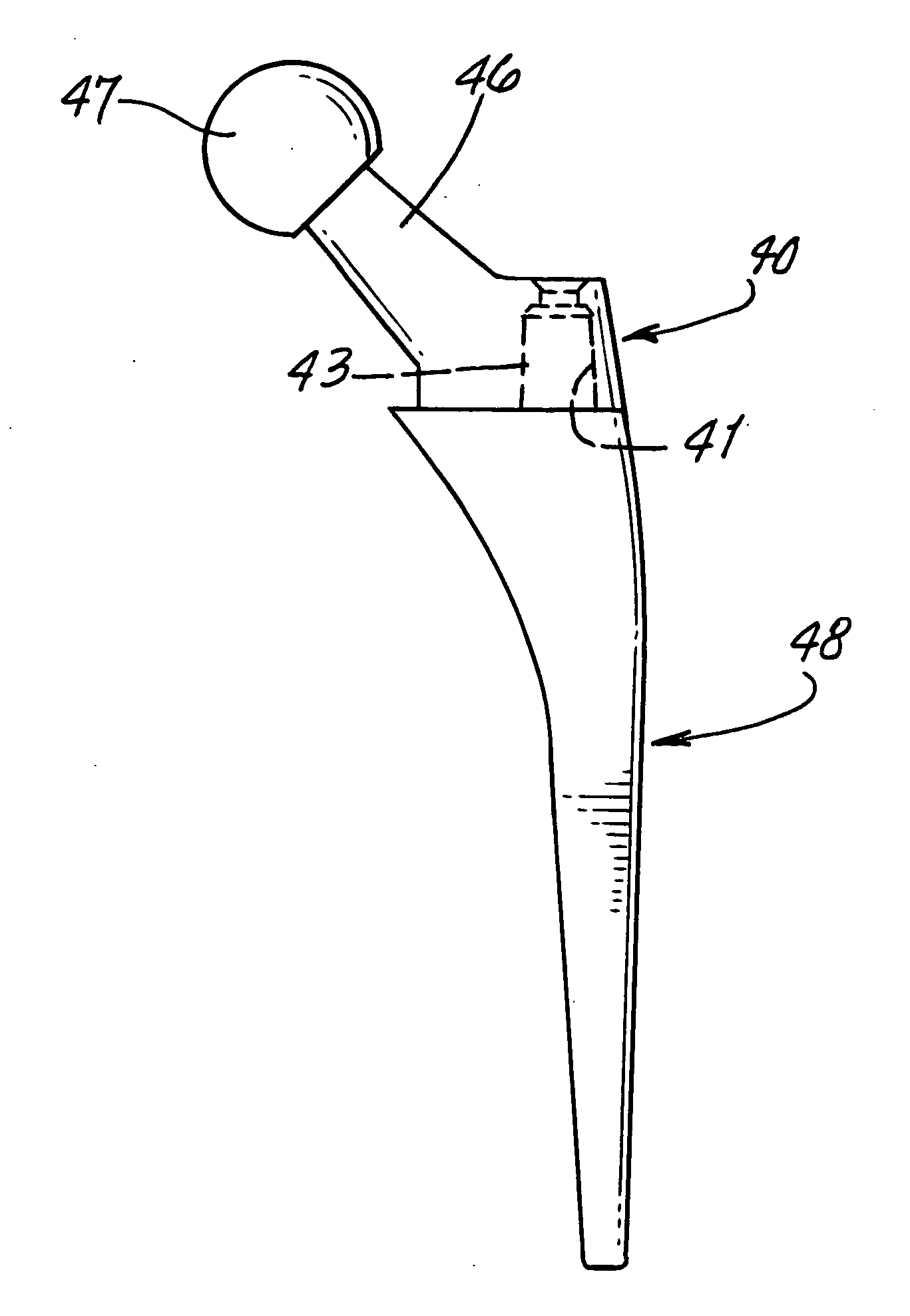
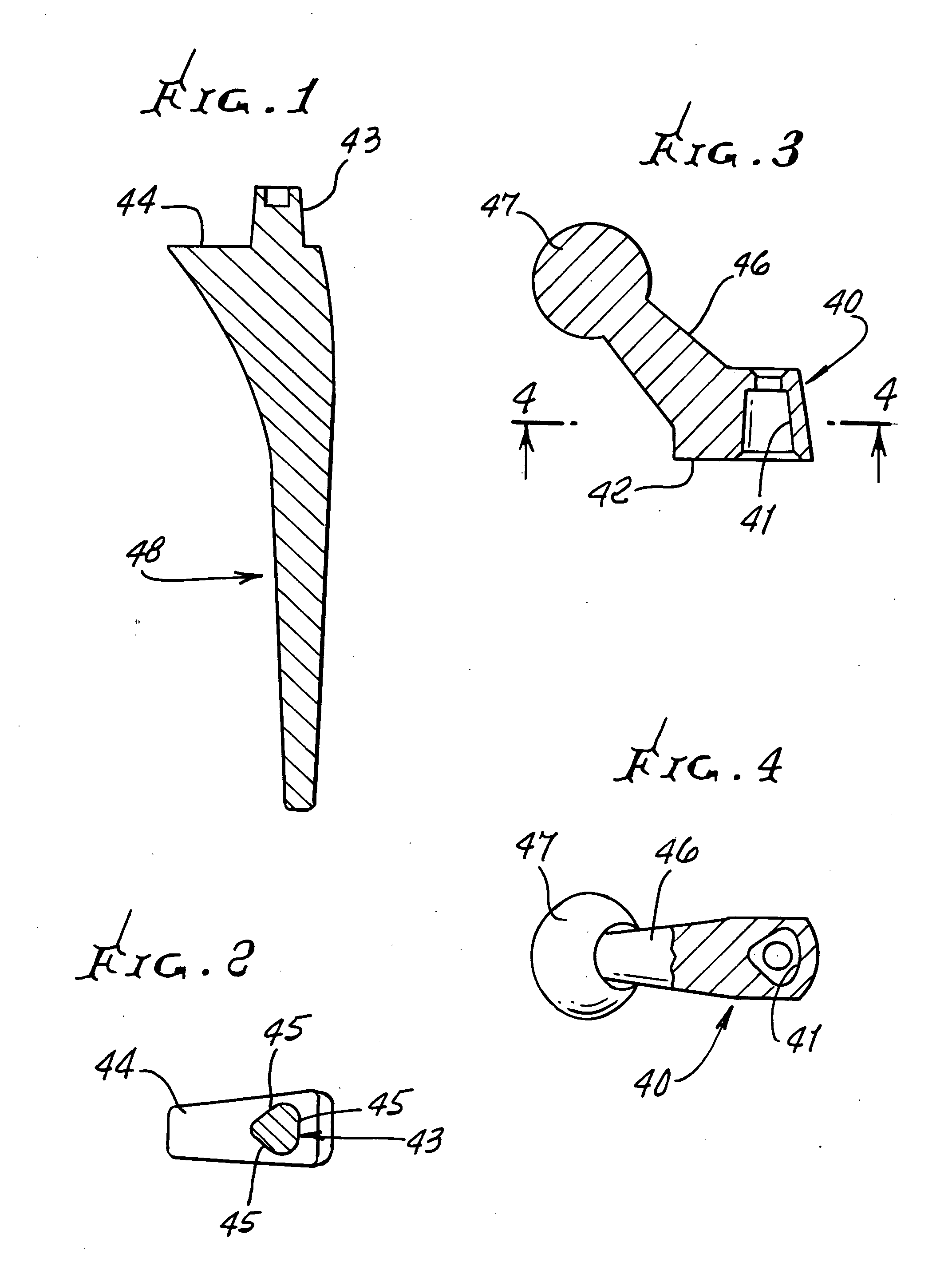
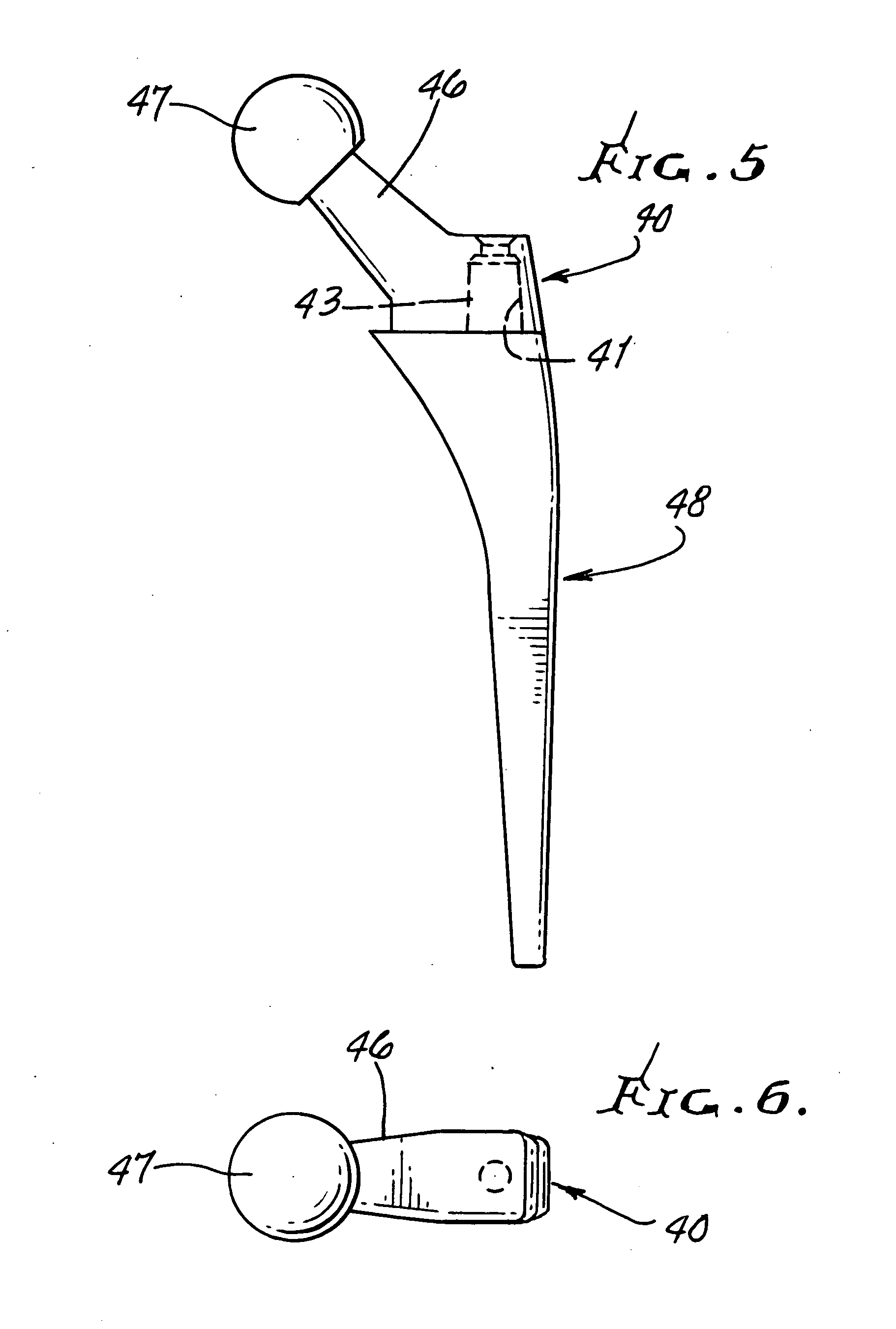
[0053]Referring first to FIGS. 19-24, hip replacement components shown include a selected size generally longitudinally extending stem 10 having an enlarged upper end 10a, and a tapered lower end 10b, to fit endwise in a corresponding recess 11 formed in a leg bone, i.e. femur 12. One laterally and upwardly extending neck 13 carrying a ball 14 is shown in FIG. 21, and these elements are also shown in FIG. 22. One size selected base 15 carries the neck and ball in FIG. 21, and another size selected base 16 carries the neck and ball in FIG. 22, the dimensions and angularity of the necks 13 in FIGS. 21 and 22 are the same, and the carried ball sizes are the same.

[0054]Base 15 is generally of rectangular block shape and has a bottom horizontal wall 18, top wall 19, an upright right end wall 20, and an upright left end wall 21. The dimension between walls 20 and 21 is indicated as x1. Base 16 is also generally of rectangular block shape, having a bottom horizontal wall 22, top horizontal...


PUM


Abstract

In a human hip replacement process, the steps include providing a selected size generally longitudinally extending stem and laterally angled neck, the stem received endwise into a recess in an elongated femur, there being a ball on the neck, the neck and stem having a non-circular tongue and groove interfit connection to resist relative rotary displacement therebetween, the connection defining a generally longitudinal axis, fitting the ball in a socket on a hip bone, to pivot in the socket, the selection of stem and neck, and tongue and groove connection between the size selected stem and neck, enabling accurate pivoting of the ball. A set of different size balls and neck units are enabled for selective choice, as during surgery.

Description

BACKGROUND OF THE INVENTION[0001]This invention relates generally to human hip replacement, and more particularly to achieving more accurate leg length restoration and joint stability, as during surgery. The invention concerns implantable orthopedic prostheses for total hip replacement and, more particularly, a prosthesis which receives a modular neck assembly selected for a desired anteversion, neck length, neck angle and offset.[0002]During such surgery, a replacement stem is employed and inserted lengthwise into a pathway in the femur. The stem carries an angularly extending i.e. offset neck, and a ball at the neck terminus, to be received into a socket defined by the joint. These components must be accurately relatively positioned to accommodate to each patient's particular femur and hip socket configuration, as during surgery, which is time consuming and subject to adjustment problems and difficulties. It is found that the stem may not seat at a local predicted by the surgery, ...

Claims


Application Information

Patent Timeline
Patent Type & Authority Applications(United States)
IPC IPC(8): A61F2/32
CPCA61F2/36A61F2002/30112A61F2002/30156A61F2002/3666A61F2002/30377A61F2002/30616A61F2002/3652A61F2002/30334A61F2002/30367A61F2002/30881
Inventor CAILLOUETTE, JAMES THOMPSONKHALILI, FARID BRUCE
Owner CAILLOUETTE JAMES THOMPSON
Why Eureka
Try Eureka