Transfer assembly

Inactive Publication Date: 2011-09-15
BLUEPRINT HLDG
View PDF10 Cites 0 Cited by
  • Summary
  • Abstract
  • Description
  • Claims
  • Application Information

AI Technical Summary

Benefits of technology

[0010]It is an object of the present invention to improve the transfer assemblies known from the prior art, as a result of which a maximum transfer capacity can be created at minimal cost, that is to say using a minimal number of transfer robots. This object is achieved, according to a first aspect, by an above-described transfer assembly comprising a supply conveyor, first and second transfer robots arranged on either side of said conveyor belt and a discharge position, wherein said robots comprise an operating area with a central area and the central areas of said transfer robots are situated one behind the other in the conveying direction of said supply conveyor, wherein a third transfer robot is provided, which is situated in a direction transversely to said conveying direction between said first and second robot, wherein the central area of said third transfer robot is situated between the central area of said first and second transfer robots in said conveying direction, wherein said discharge position comprises a discharge conveyor and that said discharge conveyor is arranged above it so as to cross the supply conveyor.
[0011]According to this aspect of the present invention, the transfer robots are positioned in such a manner that the operating range of the robots together delimits a track which extends at an angle to the supply conveyor which is not perpendicular. As a result thereof, each of the transfer robots can be active while travelling a small path while still covering the entire area of the supply conveyor in a simple manner. All robots are displaced with respect to one another, both in the conveying direction and at right angles thereto.
[0012]Preferably, the operating areas of the transfer robots overlap one another, viewed in the conveying direction of the supply conveyor. However, due to the positioning according to the present invention, these operating areas are situated slightly behind one another. This means that the flow of goods which could not be handled by the transfer robot situated furthest upstream due to lack of capacity, can still be grasped by the subsequent transfer robot or transfer robots and be displaced in the desired manner. This makes the system very secure. The same applies to the third transfer robot, the operating range of which (partly) coincides with that of the second transfer robot. As a result thereof, the second transfer robot mainly acts as a safeguard, that is to say to prevent goods from being conveyed by the supply conveyor without having been treated, which is undesirable. However, by observing the products and using a suitable control unit, this second transfer robot can perform a substantial part of the operations. Obviously, there will always have to be sufficient space on the discharge conveyor to place the product from the robot situated furthest downstream. The number of transfer robots can be selected as a function of the width of the supply belt. In principle, there is no maximum number, but preferably at most 6-10 of such robots are used.
[0018]By means of the invention, it is possible to transfer large numbers of products from a very wide supply belt to a narrow discharge belt without the robots having to make large turns. As a result thereof, the operating area of the robots can also remain small, making it possible to use small and quick robots which, in addition, are relatively inexpensive.

Problems solved by technology

This means that the first robot which is furthest upstream carries out most of the transfer work while the robot which is situated furthest downstream mainly functions as a safeguard to prevent products from not being transferred, which is undesirable.

Method used


Image

  • Transfer assembly
  • Transfer assembly

Examples


Embodiment Construction

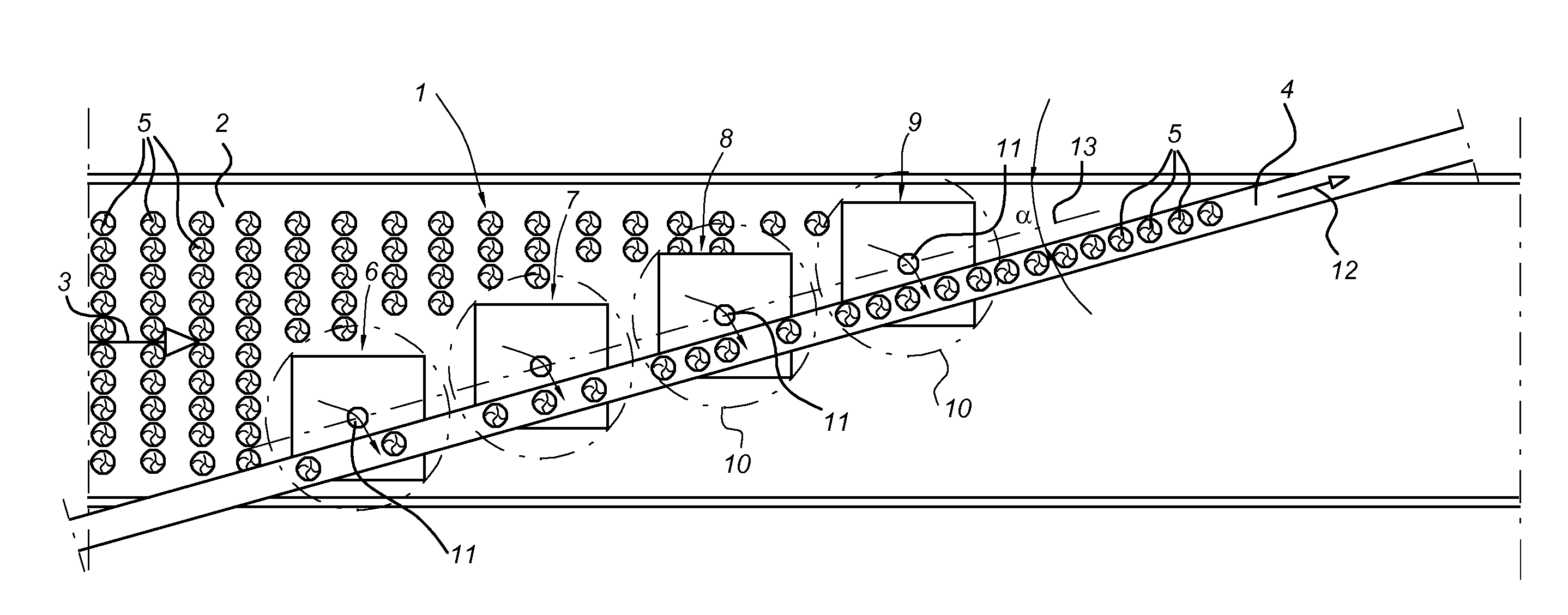
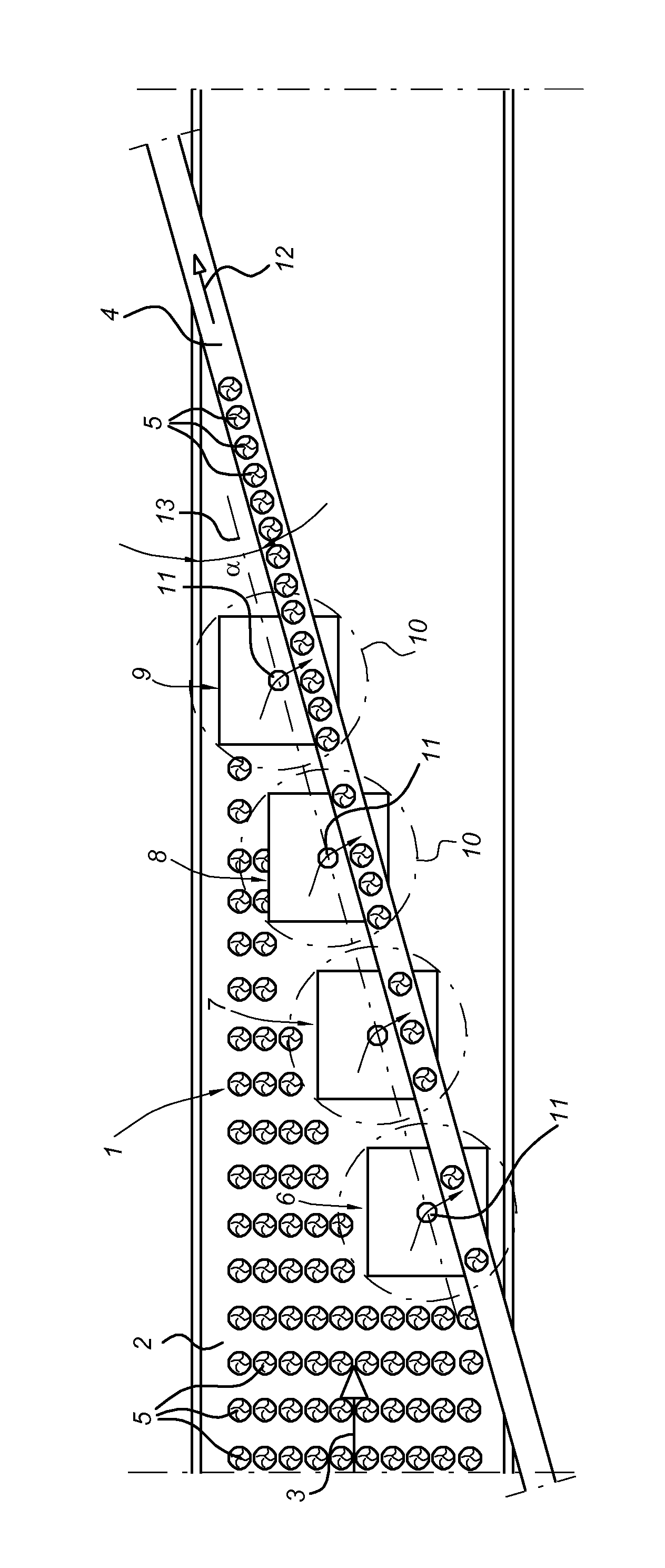
[0022]In the sole FIGURE, reference numeral 1 denotes the transfer assembly according to the invention. It consists of a supply conveyor 2 which moves a large number of products 5 in the direction of arrow 3 which are arranged in a number of parallel rows. A discharge conveyor 4 is arranged in such a manner that it is situated above the supply conveyor 2 and is moved at greater speed than the supply conveyor in the direction of arrow 12. The return part of belt 4 may be below the conveyor belt 2 or between the supply and return part of belt 2. A number of transfer robots are present, such as pick-and-place robots 6-9. In this case, the two “outermost” robots 6 and 9 are denoted as first robot 6 and second robot 9. According to the present invention, the intermediate transfer robots 7 and 8 are positioned such that they are not situated on a side of the supply conveyor, but in an area which extends at an angle with respect to the supply conveyor. In other words, the range of each rob...


PUM


Abstract

Transfer assembly for transferring large numbers of products from a supply conveyor to a further position, such as one or more discharge conveyors. It is proposed to use a number of pick-and-place robots to this end, wherein the adjacent operating ranges are positioned along a line, which line extends at a small angle to the conveying direction. Preferably, the discharge conveyor extends parallel to the line and crosses the supply conveyor and is situated above it. In this way, it is possible to transfer large numbers of products using a limited number of transfer robots and to guarantee that all products are removed from the supply conveyor.

Description

BACKGROUND OF THE INVENTION[0001]The present invention relates to a transfer assembly.[0002]Such transfer assemblies are generally known in the prior art and are used in cases where large numbers of products have to be removed from a supply conveyor and have to be placed elsewhere. Placing products elsewhere may comprise placing them in some form of packaging, but may also comprise “narrowing” a wide row of products to form a narrower row of products.[0003]If the supply conveyor has a large capacity, it has been found to be practical to use various transfer robots, such as pick-and-place robots. In certain embodiments, these are arranged in such a manner that certain transfer robots are situated upstream with respect to other robots. This means that the first robot which is furthest upstream carries out most of the transfer work while the robot which is situated furthest downstream mainly functions as a safeguard to prevent products from not being transferred, which is undesirable. ...

Claims


Application Information

Patent Timeline
IPC IPC(8): B65G47/53B65G47/52
CPCB65G47/682B65G47/53
Inventor FORTMAN, RONALD
Owner BLUEPRINT HLDG
Why Eureka
Try Eureka