Oil-gas pipeline monitoring system based on optical fiber

A technology for oil and gas pipelines and monitoring systems, applied in pipeline systems, gas/liquid distribution and storage, mechanical equipment, etc., can solve the problems of economic loss, long transmission distance, poor anti-interference ability, etc., to prevent theft and damage incidents , The effect of large transmission capacity and small transmission loss

Inactive Publication Date: 2015-12-02
CHENGDU QIANYI INFORMATION TECH
View PDF8 Cites 9 Cited by
  • Summary
  • Abstract
  • Description
  • Claims
  • Application Information

AI Technical Summary

Problems solved by technology

The existing oil and gas pipelines have long transmission distances and complex environments, so online monitoring and alarming of pipelines require high technical requirements
Traditional monitoring methods mainly include manual inspection, buried point-type vibration detection and alarm, etc. Such methods are not only costly, waste of human and financial resources, but also low in automation, poor in anti-interference ability, and low in sensitivity
Traditional open-air oil and gas pipelines are widely distributed, long in length, and difficult to manage. Due to various natural factors, pipelines will move, resulting in leakage accidents at pipeline connections. However, the inspection workload for pipeline leakage is very large, but there is a lack of Effective monitoring of leakage, oil and gas leakage will not only bring economic losses, but also cause pollution to the environment

Method used


Image

  • Oil-gas pipeline monitoring system based on optical fiber

Examples


Embodiment Construction

[0015] The following will clearly and completely describe the technical solutions in the embodiments of the present invention with reference to the accompanying drawings in the embodiments of the present invention. Obviously, the described embodiments are only some, not all, embodiments of the present invention. Based on the embodiments of the present invention, all other embodiments obtained by persons of ordinary skill in the art without making creative efforts belong to the protection scope of the present invention.

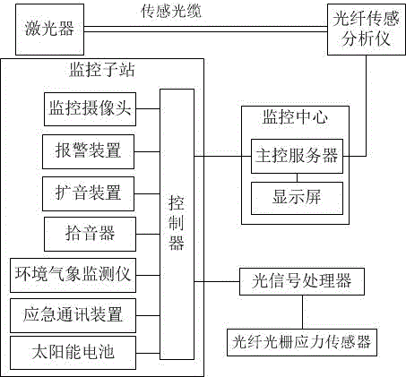
[0016] 2. If figure 1 An optical fiber-based oil and gas pipeline monitoring system shown is characterized in that it includes a monitoring center, a plurality of monitoring sub-stations, an optical fiber sensing analyzer, a laser, a sensing optical cable, a fiber grating stress sensor, and an optical signal processor. The monitoring center is equipped with a main control server and a display screen, and a controller monitoring camera, an alarm device, a sound...


PUM


Abstract

The invention relates to an oil-gas pipeline monitoring system based on optical fiber. The oil-gas pipeline monitoring system is characterized by comprising a monitoring center, a plurality of monitoring substations, an optical fiber sensing analyzer, a laser device, a sensing optical cable, an fiber bragg grating sensor and an optical signal processor, wherein the monitoring center is provided with a master control server and a display screen; a controller monitoring camera, an alarm device, a sound pickup device and a sound amplification device are arranged in each monitoring substation; the controllers are connected with the monitoring cameras, the alarm devices, the sound pickup devices, the sound amplification devices and the optical signal processor in sequence; the optical signal processor is connected with the fiber bragg grating sensor through optical fiber. Through the oil-gas pipeline monitoring system, the fiber bragg grating sensor is arranged on an oil-gas conveying pipeline; the stress state of the pipeline is analyzed by monitoring the stress change of the pipeline and is warned in advance, so that operators can maintain the pipeline in time, so that the danger caused by damage to the pipeline and the leakage of the oil and the gas can be reduced.

Description

technical field [0001] The invention relates to the technical field of oil and gas pipeline monitoring, in particular to an optical fiber-based oil and gas pipeline monitoring system. Background technique [0002] Oil and gas pipelines are responsible for the transmission of a large number of oil and gas resources in the country, which is related to national security, economic and social harmony, stability and development. Effective anti-theft and anti-dig damage early warning monitoring of oil and gas pipelines can effectively avoid or reduce losses. The existing oil and gas pipelines have long transmission distances and complex environments, so online monitoring and alarming of pipelines require high technical requirements. Traditional monitoring methods mainly include manual inspection, buried point-type vibration detection and alarm, etc. These methods are not only costly, waste of human and financial resources, but also have low degree of automation, poor anti-interfere...

Claims


Application Information

Patent Timeline
Patent Type & Authority Applications(China)
IPC IPC(8): F17D5/02
Inventor 莫尚毅
Owner CHENGDU QIANYI INFORMATION TECH
Why Eureka
Try Eureka