Route Planning Device and Route Planning System

a technology of route planning and planning device, which is applied in the direction of navigation instruments, instruments, battery/fuel cell control arrangement, etc., can solve the problems of electric vehicles being stranded, processing load on the onboard terminal, and corresponding power requirements every time the subject vehicle position changes, and the effect of affecting the operation of the vehicl

Active Publication Date: 2011-09-15
HITACHI LTD
View PDF4 Cites 178 Cited by
  • Summary
  • Abstract
  • Description
  • Claims
  • Application Information

AI Technical Summary

Benefits of technology

According to the 2nd aspect of the present invention, in the route planning device according to the 1st aspect, it is preferred that the waypoint is a node included in the minimum-cost route; the plurality of facilities satisfy a predetermined search condition set by the search unit; and a cost of the guided route from the waypoint to the each of the plurality of facilities is smaller than a cost of a guided route from the waypoint to another facility satisfying the predetermined search condition.
According to the 10th aspect of the present invention, in the route planning system according to the 9th aspect, it is preferred that the waypoint is a node included in the minimum-cost route; the plurality of facilities satisfy a predetermined search condition set by the search unit; and a cost of the guided route from the waypoint to the each of the plurality of facilities is smaller than a cost of a guided route from the waypoint to another facility satisfying the predetermined search condition.

Problems solved by technology

However, the method described above, in which charging station information is collected as the remaining battery power in the electric vehicle becomes low, may give rise to an undesirable situation in which there is no charging station close enough for the vehicle to reach on its remaining power, and the electric vehicle will be stranded.
However, the processing load on the onboard terminal that calculates the route from the subject vehicle position to a charging station and the corresponding power requirement every time the subject vehicle position changes is bound to be very large.

Method used


Image

  • Route Planning Device and Route Planning System
  • Route Planning Device and Route Planning System
  • Route Planning Device and Route Planning System

Examples


first embodiment

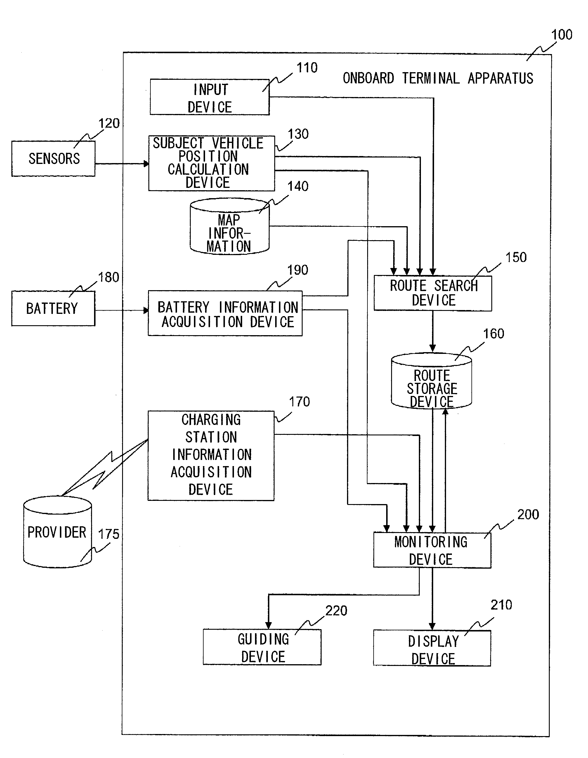
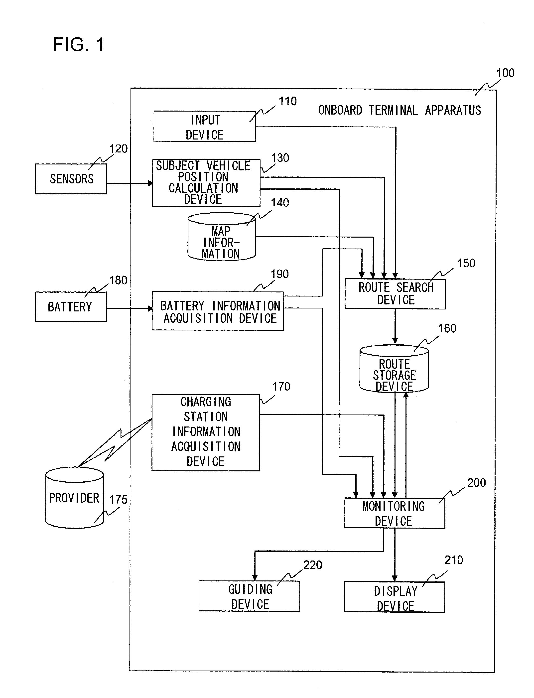
FIG. 1 shows the overall structure of the route planning device according to the present invention, configured as an onboard terminal apparatus in the first embodiment. The onboard terminal apparatus 100 comprises an input device 110, a subject vehicle position calculation device 130, map information 140, a route search device 150, a route storage device 160, a charging station information acquisition device 170, a battery information acquisition device 190, a monitoring device 200, a display device 210 and a guiding device 220.

The onboard terminal apparatus 100, sensors 120 and a battery 180 are connected with one another via a cabin internal network such as a CAN. The onboard terminal apparatus 100, the sensors 120 and the battery 180 may be directly connected with one another or they may be connected via relay devices.

The input device 110 is a means by which the user is able to enter, through a user interface at the onboard terminal, instructions for setting a destination, select...

second embodiment

The route planning system according to the present invention is achieved as a route search system in the second embodiment. The route search system in the embodiment includes an onboard terminal apparatus 100 shown in FIG. 16A and a center apparatus 300 shown in FIG. 16B. The onboard terminal apparatus 100 comprises an input device 110, a subject vehicle position calculation device 130, map information 140, a route storage device 160, a charging station information acquisition device 170, a battery information acquisition device 190, a monitoring device 200, a display device 210, a guiding device 220 and a communication device 310.

The center apparatus 300 includes map information 140, a route search device 150, a route storage device 160 and a communication device 310.

The onboard terminal apparatus 100 and the center apparatus 300 are connected with each other through communication achieved via the communication devices 310. The communication devices 310 may each be constituted with...


PUM


Abstract

A route planning device includes: a search unit that searches for a plurality of facilities located near the minimum-cost route from a current position to the destination, where the battery can be charged; a guided route calculation unit that sets a waypoint on the minimum-cost route via which the moving object can be guided to each facility, and calculates a guided route from the waypoint to the each facility and a first power requirement indicating an amount of power required to travel through the guided route; and a facility designating unit that designates a target facility to which the moving object is to be guided, based upon third power requirements each calculated by adding a second power requirement, indicating an amount of power required to allow the moving object to travel from the current position to the waypoint, to the first power requirement and remaining power in the battery.

Description

INCORPORATION BY REFERENCEThe disclosure of the following priority application is herein incorporated by reference: Japanese Patent Application No. 2010-052122 filed Mar. 9, 2010.BACKGROUND OF THE INVENTION1. Field of the InventionThe present invention relates to a route planning device and a route planning system with which an electric vehicle traveling on a route calculated to take the electric vehicle from a start point to a destination is monitored to ascertain whether or not the electric vehicle is able to travel to a nearby charging station.2. Description of Related ArtThe traveling range of an electric vehicle is normally shorter than that of an automobile equipped with an internal combustion engine. In addition, the electric vehicle needs to be charged at a special charging station. This means that the electric vehicle may need to make frequent stops at charging stations before it reaches the destination.Onboard terminal apparatuses for electric vehicles in the known art inc...

Claims


Application Information

Patent Timeline
Patent Type & Authority Applications(United States)
IPC IPC(8): G01C21/36
CPCG01C21/3469Y02T10/7258G01C21/3476B60L2240/622B60L2240/70B60L2240/72B60L2250/16B60L2260/52B60L2260/54Y02T90/16Y02T10/7072Y04S30/14B60L53/665B60L58/12Y02T10/70Y02T10/72Y02T90/167Y02T90/12Y02T90/14
Inventor HIRUTA, TOMOAKIOKUDE, MARIKOKUMAGAI, MASATOSHI
Owner HITACHI LTD
Why Eureka
Try Eureka