Route planning system and method for agricultural working machines

a technology for agricultural working machines and planning systems, applied in traffic control systems, computation using non-denominational number representations, analog and hybrid computing, etc., can solve problems such as the inability to use systems of this type to perform advance, and achieve the effect of simplifying computation steps, reducing the amount of memory required, and reducing computing effor

Active Publication Date: 2005-12-08
CLAAS SELBSTFAHRENDE ERNTEMASCHINEN GMBH
View PDF3 Cites 99 Cited by
  • Summary
  • Abstract
  • Description
  • Claims
  • Application Information

AI Technical Summary

Benefits of technology

[0017] The fact that the route planning system is also configured such that it recognizes driving routes and working strategies considerably reduces the amount of computing effort required to determine the driving paths that form the driving route. In this context, a particularly efficient route planning system is created when the route planning system can access stored driving strategies that define either the interplay of working machines working simultaneously or in succession in the particular territory and defines their optimal driving routes in the particular territory.
[0018] To simplify the computation steps and to depict them visually, a “master line” is defined to determine the driving route in the route planning system. The further driving paths are depicted such that they are offset from this master line by the working width or a multiple of the working width of the agricultural working machine. In an advantageous further development of the present invention and with the same effects, the master line, which is drawn straight or curved, is defined by at least two path points separated by a distance, whereby the virtual extension of the master line through these two path points that are separated by a distance serves as a guide line, based on the orientation of which the agricultural working machine is guided on the territory to be worked. In the simplest case, the operator of the agricultural working machine defines the master line by entering coordinates.
[0019] To reduce the amount of memory required and to accelerate the computation process to determine the driving route, algorithms are stored in the route planning system that reduce the path points required to depict curved master lines with consideration for the necessary accuracies.
[0020] To obtain driving routes having a transparent structure and a re...

Problems solved by technology

It was not possible to use systems of this type to...

Method used


Image

  • Route planning system and method for agricultural working machines
  • Route planning system and method for agricultural working machines
  • Route planning system and method for agricultural working machines

Examples


Embodiment Construction

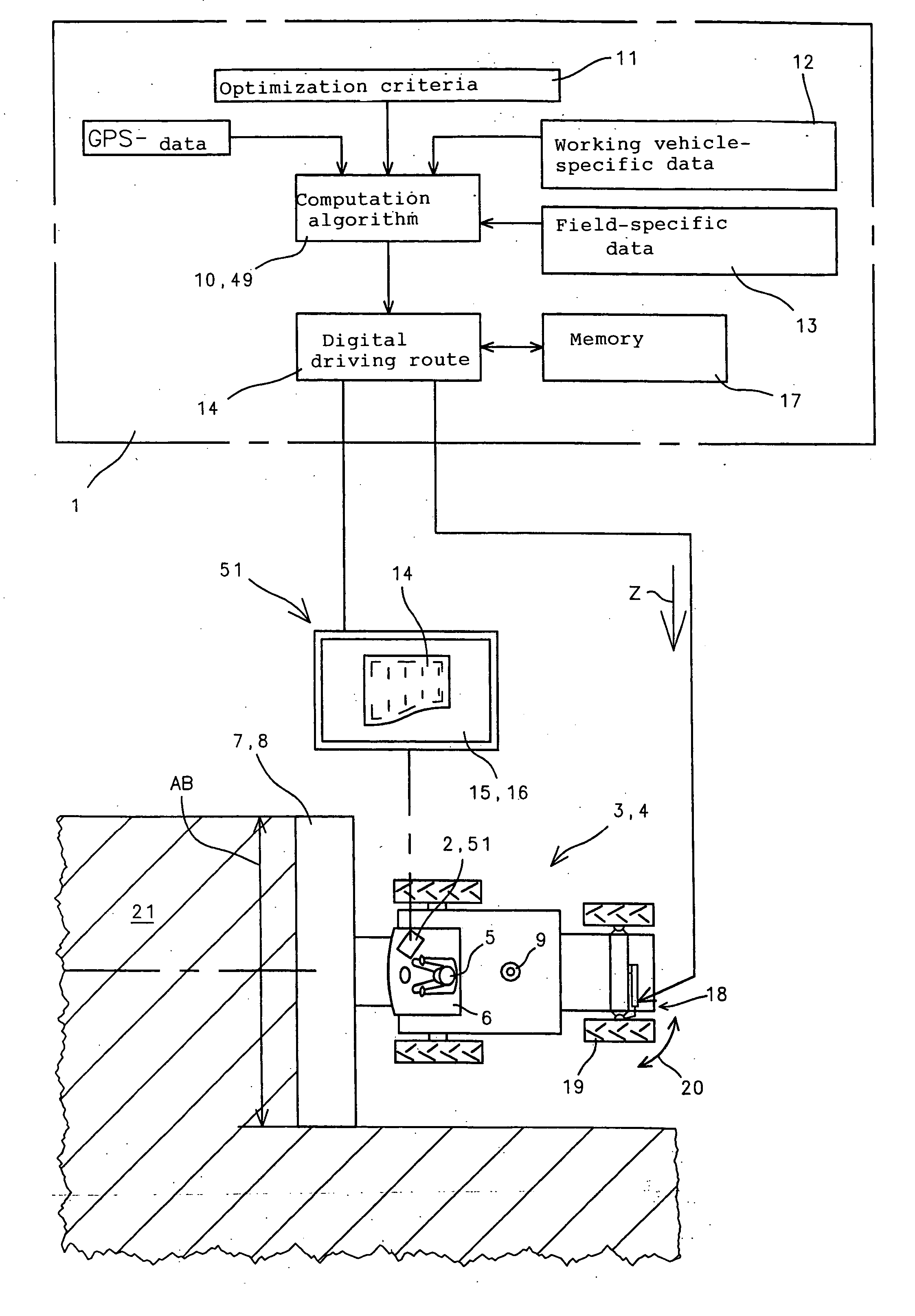
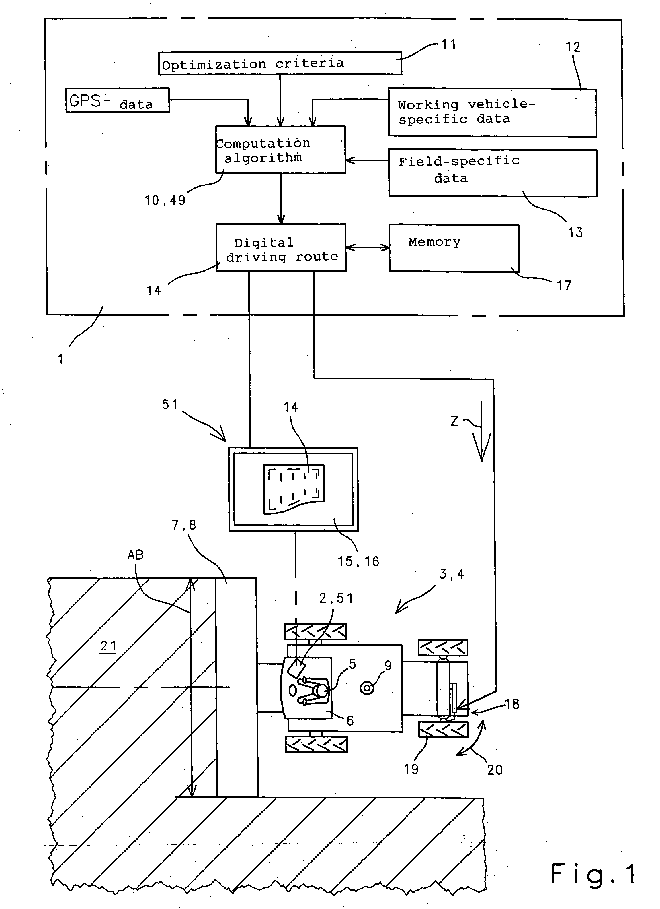
[0031]FIG. 1 shows a schematic representation of route planning system 1, which implements route planning method and was made known in EP 0 821 296, and which is integrated in an arithmetic and display unit 2 of an agricultural working machine 4 configured as a combine harvester 3. Arithmetic and display unit 2 is located in driver's cabin 6, within viewing and operating distance of operator 5 of combine harvester 3. An attachment 8, which is configured, e.g., as a grain cutting device, is assigned to the front side of combine harvester 3, the width of the attachment determining the working width AB of combine harvester 3. In addition, agricultural working machine 4 includes a “GPS” antenna 9 for receiving position coordinates via GPS.

[0032] According to an enlarged section outlined with dashed lines in FIG. 1, the route planning system includes one or more computation algorithms 10 that generate position coordinates of agricultural working machine 4 in a manner known per se based ...


PUM


Abstract

In a route planning system and method for agricultural working machines, a defined working width is assigned to the agricultural working machines to generate driving routes in a territory, and dynamic adaptation of the planned driving route is carried out thereby ensuring that the driving route to be covered is flexibly adaptable to changing external conditions such as driving around obstacles, thereby largely relieving the operator of the agricultural working machine of the task of performing laborious steering maneuvers.

Description

BACKGROUND OF THE INVENTION [0001] The present invention relates to a route planning system and method for agricultural working machines. [0002] It was already known from EP 0 660 660 to equip agricultural working machines with “GPS” systems to record the position of the agricultural harvesting machine in an area to be worked. In this process, the operator of the machine determined the route to be driven, and the GPS system—that is actively connected to a recording unit—delivered the position data of the vehicle, which were then used in the recording unit to electronically depict the driving path that had been covered. Systems of this type were an initial step in the direction toward recording driving routes, whereby the initial application was only to record driving routes. It was not possible to use systems of this type to perform advance planning of driving routes to be worked. [0003] Building logically on the idea of displaying driving routes, systems as described in EP 0 821 29...

Claims


Application Information

Patent Timeline
IPC IPC(8): A01B69/00G01C21/20G01C22/00
CPCG01C21/20A01B69/007
Inventor DIEKHANS, NORBERTHUSTER, JOCHENBRUNNERT, ANDREAS
Owner CLAAS SELBSTFAHRENDE ERNTEMASCHINEN GMBH
Why Eureka
Try Eureka