connector

a technology of connecting rods and connecting rods, applied in the direction of couplings, mechanical equipment, earthwork drilling and mining, etc., can solve the problems of time-consuming screwing one part onto the other, requiring significant physical exertion by the operator, and the coupling is difficult and time-consuming for the operator to assemble and disassemble, so as to achieve quick and easy use and less physical exertion

Inactive Publication Date: 2011-09-22
WEATHERFORD U S INC
View PDF1 Cites 37 Cited by
  • Summary
  • Abstract
  • Description
  • Claims
  • Application Information

AI Technical Summary

Benefits of technology

[0040]It will be understood that it is common practice to change tools often when using a wireline lubricator and so the process described above may be undertaken many times during a single operation. According

Problems solved by technology

While such a connecting mechanism is adequate in many circumstances, the act of screwing one part onto the other can be time-consuming and can require significant physical exertion for an operator, particularly when large and/or heavy parts are involved.
However, such couplings are difficult and time-consuming for an operator to assemble and dis

Method used


Image

  • connector
  • connector
  • connector

Examples


Embodiment Construction

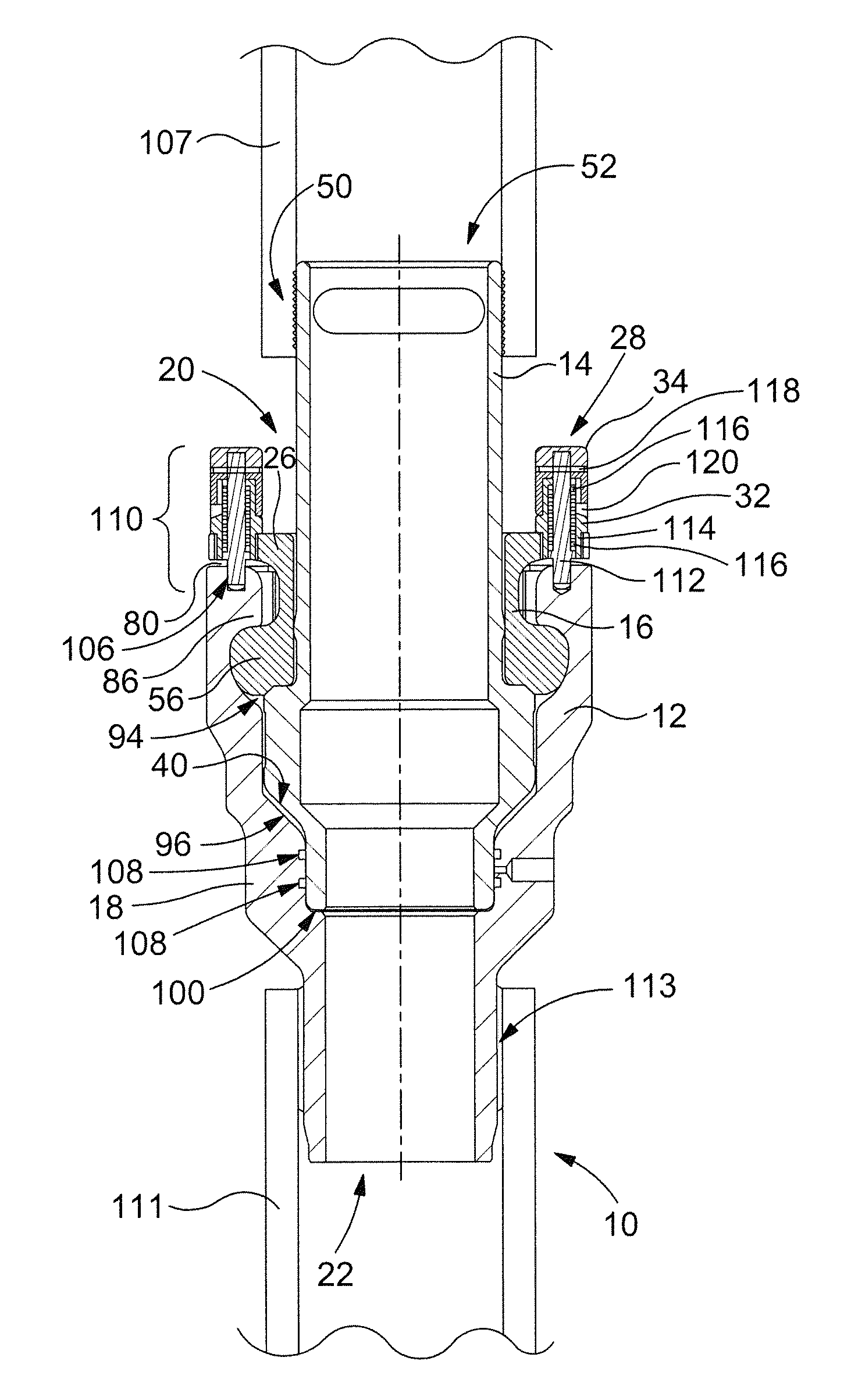
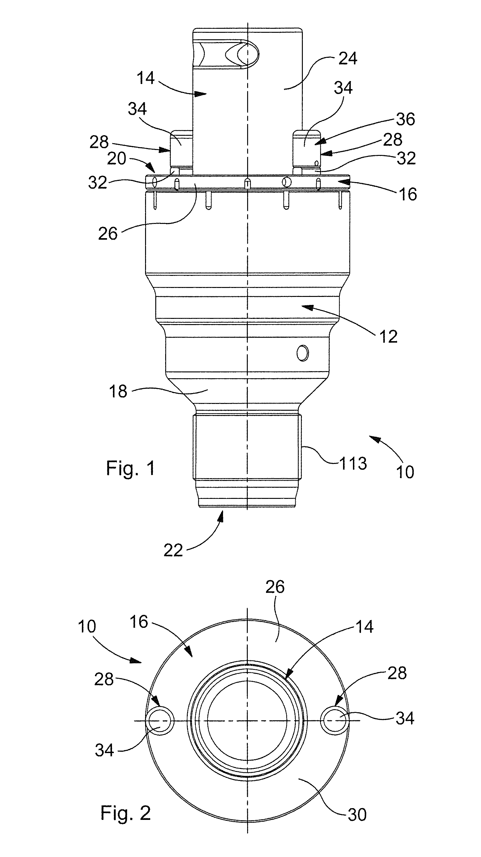
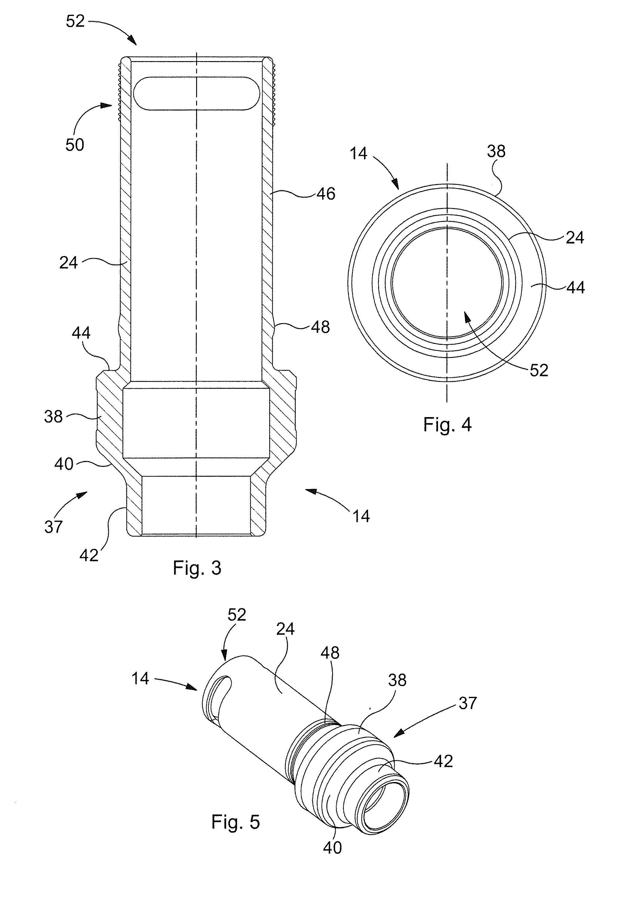
[0058]With reference to FIG. 1, there is illustrated an assembled connector 10 according to a first embodiment of the present invention. The connector 10 comprises a female component 12, a male component 14 and a collet 16. The female component 12 has a hollow generally tubular body 18 which is wider at an upper end 20 than at a lower end 22. The male component 14 also comprises a generally tubular body 24, the nose (not shown) of which is inserted into the upper end 20 and received within the female component 12, as illustrated. The collet 16 is located between the male component 14 and the female component 12 such that only its outer flange 26 is visible in FIG. 1. The male component 14, collet 16 and female component 12 will be described in more detail below in relation to subsequent figures.

[0059]Also shown in FIGS. 1 and 2 are two diametrically opposed handles 28 extending in a longitudinal direction from the exposed transverse surface 30 of the collet 16. The handles 28 each c...


PUM

PropertyMeasurementUnit
Gravityaaaaaaaaaa

Abstract

A connector comprises a male component, a female component configured to receive an end portion of the male component, and a rotatable collet mounted on the male component. The collet and the female component comprise respective complementary inter-engaging lugs configured to secure the male and female components together in an engaged position. A latch is provided on the collet to lock the male and female components together.

Description

CROSS REFERENCE TO RELATED APPLICATIONS[0001]The present application claims priority to United Kingdom Patent Application No. GB1004756.1 filed on 22 Mar. 2010, the contents of which are incorporated herein by reference.FIELD OF THE INVENTION[0002]This invention relates to a connector. Particularly, but not exclusively, the invention relates to a lubricator or an assembly of temporary surface pressure control equipment (for slickline, wireline and braided cable operations) incorporating the connector and a method of operating the connector.BACKGROUND TO THE INVENTION[0003]The problem of physically connecting one part, such as a pipe, to another has historically been resolved (across all engineering disciplines) by means of a screw-threaded engagement. This requires one part to include a helical projection (i.e. thread) and the other to include a complementary recess such that relative rotation or screwing of one part with respect to the other permits engagement therebetween. While s...

Claims


Application Information

Patent Timeline
IPC IPC(8): B23P11/00F16L37/00
CPCE21B33/072F16L37/113Y10T29/49947Y10T29/49826E21B33/038F16L37/10F16L37/107
Inventor DARNELL, DAVID TREVOR
Owner WEATHERFORD U S INC
Why Eureka
Try Eureka