Turbocharger control

a technology for turbochargers and control systems, applied in electric control, combustion engines, machines/engines, etc., can solve the problems of less predictable wastegate operation than desired, improve engine torque/power output density, increase the pressure in the intake manifold, and increase the flow of air into the engine.

Active Publication Date: 2011-09-22
FORD GLOBAL TECH LLC
View PDF12 Cites 34 Cited by
  • Summary
  • Abstract
  • Description
  • Claims
  • Application Information

AI Technical Summary

Benefits of technology

[0002]Engines may use a turbocharger to improve engine torque / power output density. In one example, a turbocharger may include a compressor and a turbine connected by a drive shaft, where the turbine is coupled to the exhaust manifold side and the compressor is coupled to the intake manifold side. In this way, the exhaust-driven turbine supplies energy to the compressor to increase the pressure in the intake manifold (e.g. boost, or boost pressure) and to increase the flow of air into the engine. The boost may be controlled by adjusting the amount of gas reaching the turbine, such as with a wastegate.
[0004]The inventors herein have recognized that the wastegate is used to control the boost pressure, and the boost pressure relative to atmospheric pressure provides the motive force for moving the wastegate. For example, the atmospheric pressure may change with altitude or weather conditions which may affect the pressure difference between boost and atmospheric pressure, and hence the ability to control the boost pressure. Additionally, a circular interaction of controlling the boost pressure with the wastegate and actuating the wastegate with the boost pressure makes the wastegate operation less predictable than desired. One approach to address the above issues is a method that includes actuating the wastegate with boost pressure generated by the turbocharger. The wastegate is adjusted according to a difference between the boost pressure and the atmospheric pressure. In this way, the interdependency between controlling the boost pressure and using the boost pressure to actuate a boost-based wastegate is reduced.

Problems solved by technology

Additionally, a circular interaction of controlling the boost pressure with the wastegate and actuating the wastegate with the boost pressure makes the wastegate operation less predictable than desired.

Method used


Image

  • Turbocharger control
  • Turbocharger control
  • Turbocharger control

Examples


Embodiment Construction

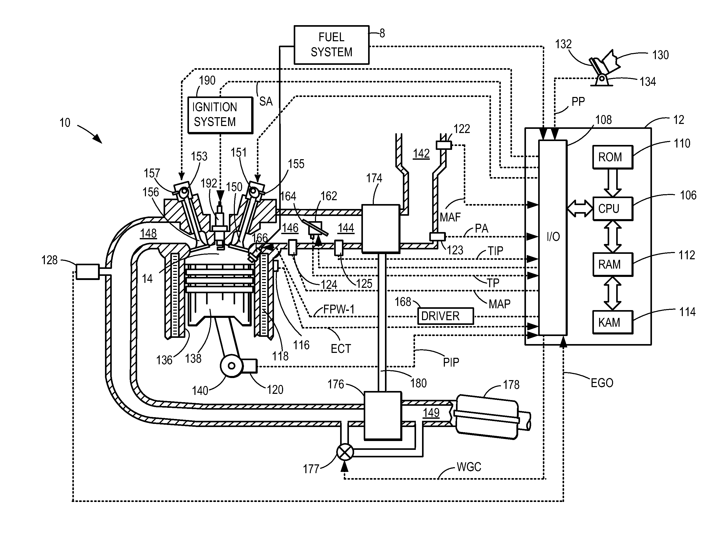
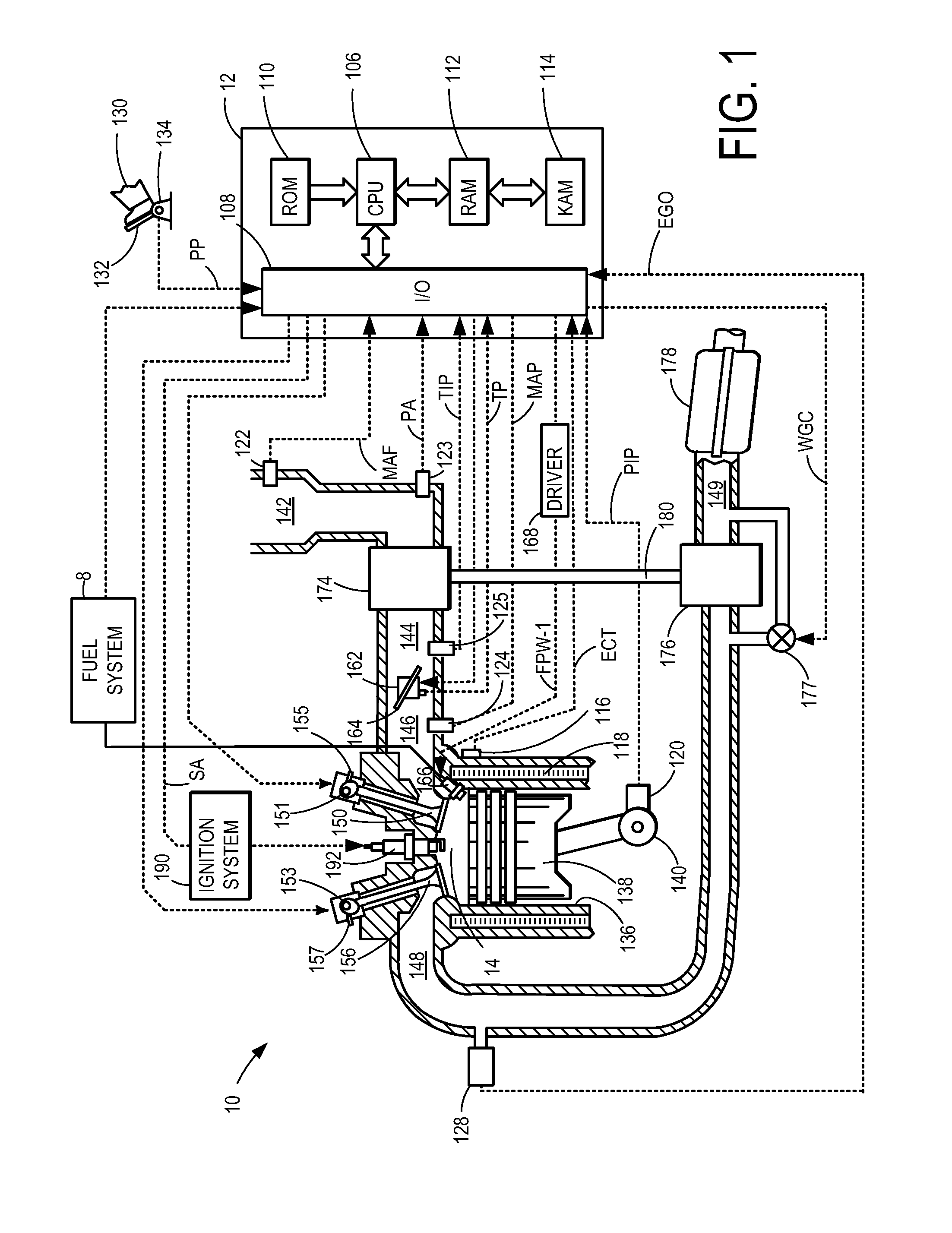
[0011]The following description relates to systems for controlling turbochargers of internal combustion engines via a wastegate. An example embodiment of an engine with a turbocharger including a wastegate is illustrated in FIG. 1. In the example configuration, the force for actuating the wastegate is provided by the boost pressure.

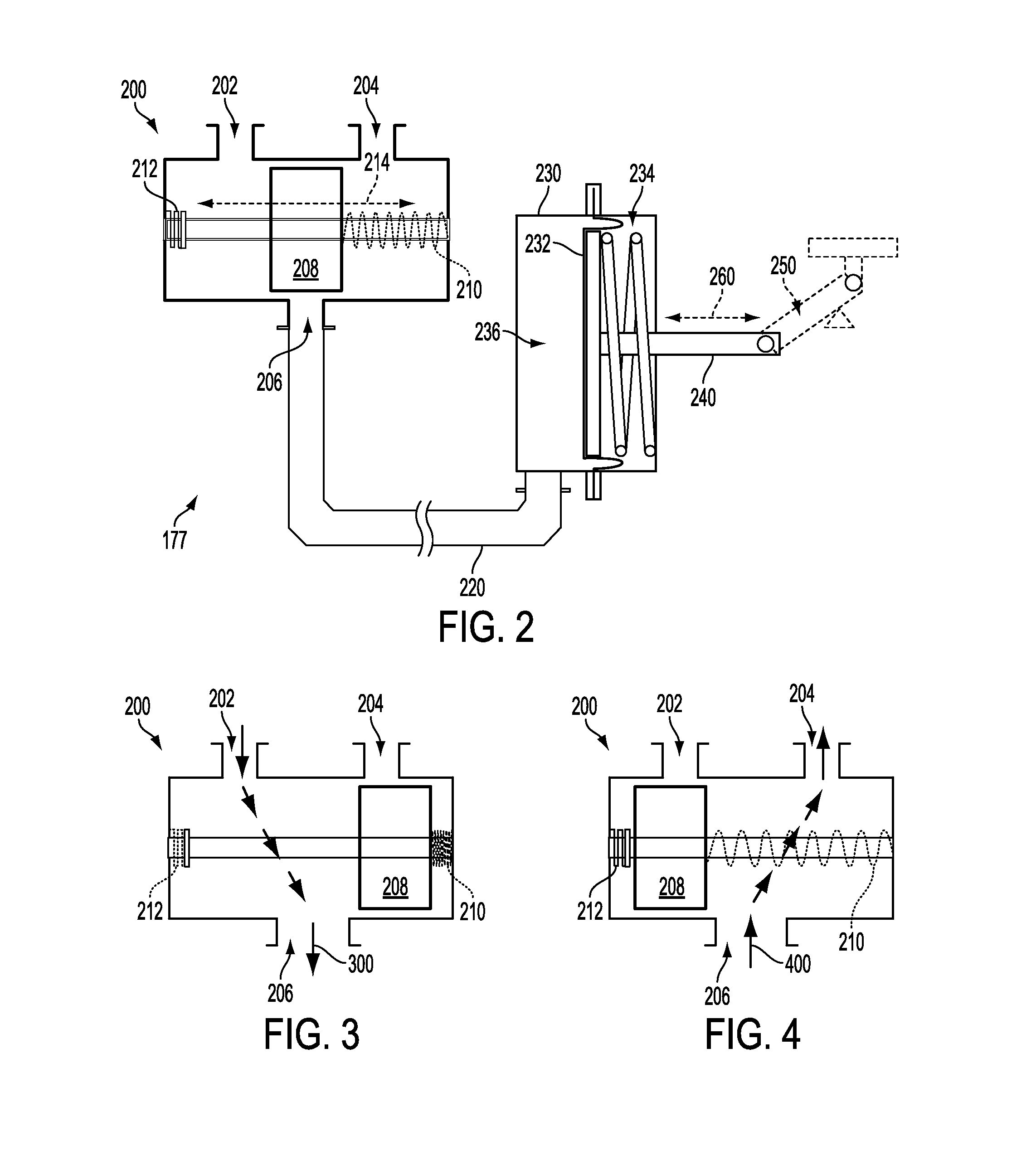
[0012]The example wastegate is shown in more detail in FIG. 2. The example wastegate comprises a solenoid valve and a wastegate canister. In FIGS. 3 and 4, the solenoid valve is shown in two positions to illustrate how the solenoid valve may be used to control the pressure of the wastegate canister. FIG. 5 illustrates prophetic data of wastegate canister pressure when the solenoid valve is modulated as described in FIGS. 3 and 4. A force generated by the wastegate canister pressure may be used to actuate the wastegate valve to control the turbocharger. The wastegate of FIG. 2 may be adjusted using a control routine, such as illustrated in FIGS. 6 and 7, f...


PUM


Abstract

Various systems and methods for controlling a turbocharger of an engine via a wastegate are described. In one example, the wastegate is adjusted according to a difference between the boost pressure and the atmospheric pressure. In this manner, the interdependency between controlling the boost pressure and using the boost pressure to actuate the wastegate in a boost-based wastegate configuration may be reduced.

Description

FIELD[0001]The present application relates to systems for controlling a turbocharger of an engine with a wastegate.BACKGROUND AND SUMMARY[0002]Engines may use a turbocharger to improve engine torque / power output density. In one example, a turbocharger may include a compressor and a turbine connected by a drive shaft, where the turbine is coupled to the exhaust manifold side and the compressor is coupled to the intake manifold side. In this way, the exhaust-driven turbine supplies energy to the compressor to increase the pressure in the intake manifold (e.g. boost, or boost pressure) and to increase the flow of air into the engine. The boost may be controlled by adjusting the amount of gas reaching the turbine, such as with a wastegate.[0003]In one example, the wastegate may include a first port coupled to boost pressure, a second port coupled to atmospheric pressure, and a valve configured to control the flow of exhaust gasses according to the wastegate duty cycle. This configuratio...

Claims


Application Information

Patent Timeline
Patent Type & Authority Applications(United States)
IPC IPC(8): F02B37/18
CPCF02B23/104F02B37/16F02B2075/125F02D13/0207Y02T10/144F02D23/02F02D41/0007F02D2200/0406F02D2200/703F02D13/0219Y02T10/12
Inventor KARNIK, AMEY Y.JANKOVIC, MRDJAN J.
Owner FORD GLOBAL TECH LLC
Why Eureka
Try Eureka