Multi-Optical Axis Photoelectric Sensor

a photoelectric sensor and optical axis technology, applied in the direction of optical detection, counting objects on conveyors, instruments, etc., can solve the problems of increased wiring cost, and deterioration of work efficiency, so as to prevent deterioration of workability of wiring work

Active Publication Date: 2011-09-22
KEYENCE
View PDF3 Cites 8 Cited by
  • Summary
  • Abstract
  • Description
  • Claims
  • Application Information

AI Technical Summary

Benefits of technology

[0018]As thus described, according to the present invention, since a single cable is all that is required to link the multi-optical axis photoelectric sensor with the external apparatus, deterioration in workability of the wiring work can be prevented.

Problems solved by technology

However, in wiring in which the phototransmitter and the photoreceiver are connected with the control panel through different cables, two cables need to be separately routed to the control panel, and the routing of the wires is thus laborious and may cause deterioration in workability of wiring work.
However, when it comes to combining cables into one cable by use of the T-branch connector, wiring cost may increase due to an increase in number of components, and the work efficiency may deteriorate due to the fact that the T-branch connector needs to be separately prepared.

Method used


Image

  • Multi-Optical Axis Photoelectric Sensor
  • Multi-Optical Axis Photoelectric Sensor
  • Multi-Optical Axis Photoelectric Sensor

Examples


Embodiment Construction

[0036]Hereinafter, a multi-optical axis photoelectric sensor 1 according to an embodiment of the present invention will be described based upon the drawings.

Outer Appearance Configuration

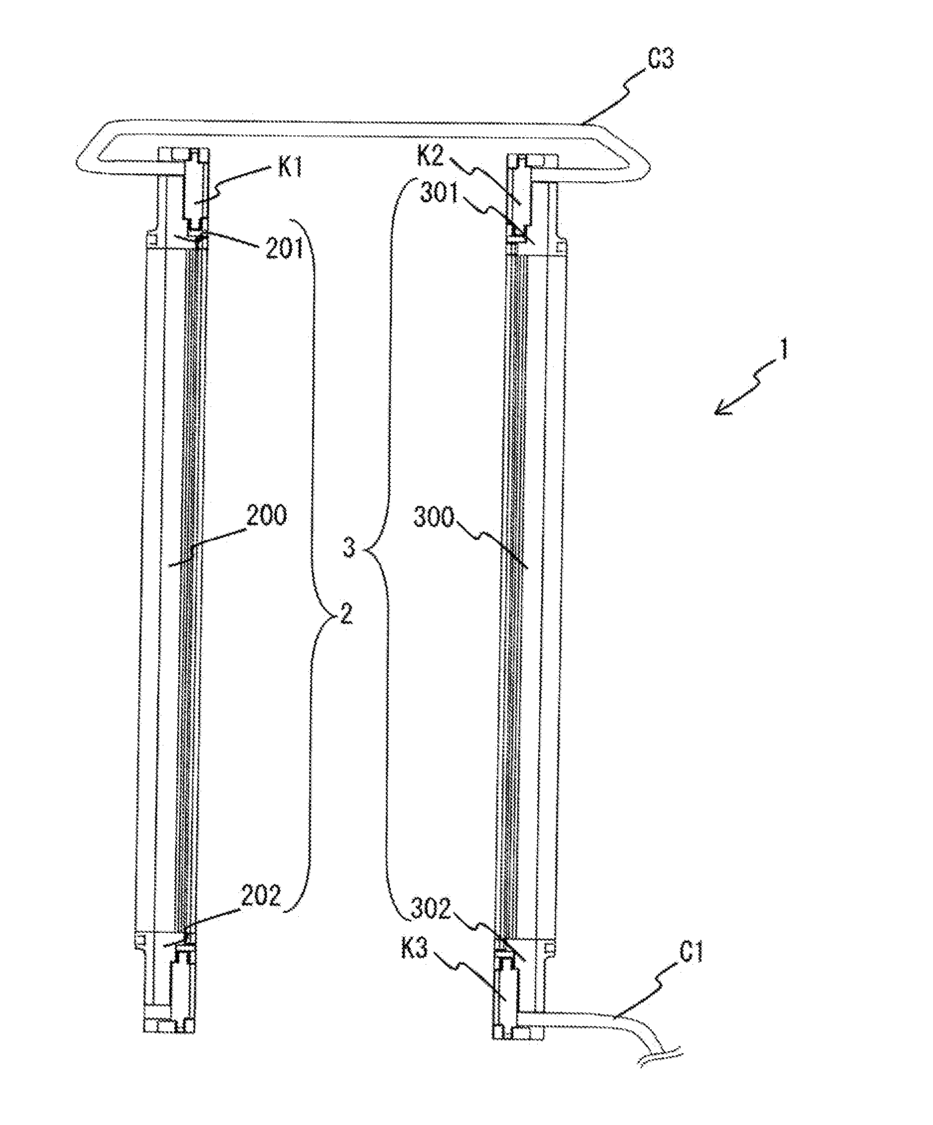
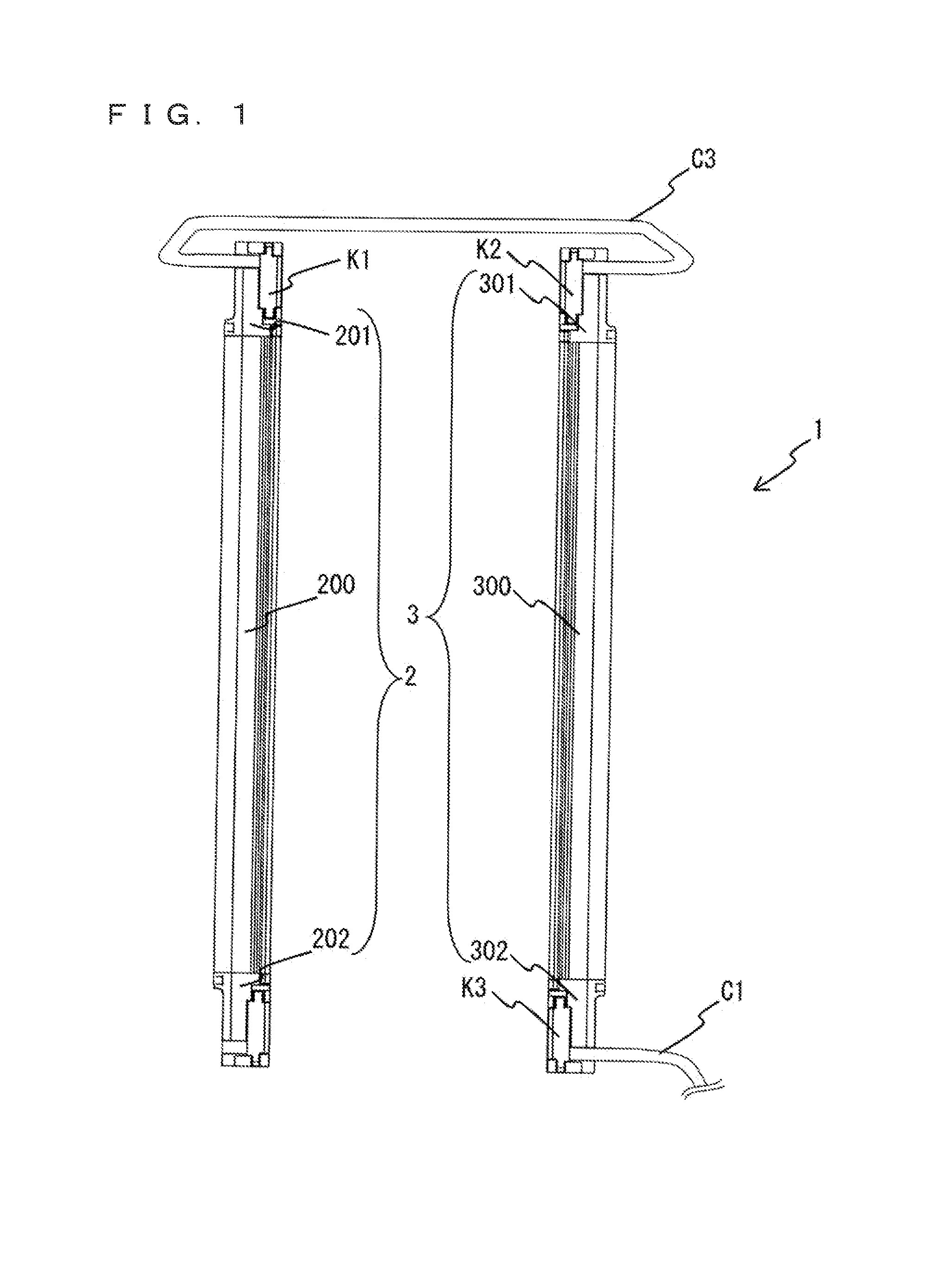
[0037]FIG. 1 is a view showing an outer appearance configuration example of the multi-optical axis photoelectric sensor 1 according to the embodiment of the present invention. As shown in FIG. 1, a multi-optical axis photoelectric sensor 1 has a phototransmitter 2 and a photoreceiver 3 which are in pairs, and the phototransmitter 2 and the photoreceiver 3 are arranged so as to be opposed to (face) each other on the same plane. For example, optical beams made up of infrared rays are emitted from a plurality of light projecting elements 23, 27 which are provided in the phototransmitter 2 (cf. FIG. 5 described later) toward a plurality of light receiving elements 33, 37 which are provided in the photoreceiver 3 so as to correspond thereto (cf. FIG. 5 described later), thereby to form a safety light cur...


PUM


Abstract

The invention provides a multi-optical axis photoelectric sensor capable of improving workability of wiring. The sensor outputs to an external apparatus a safe signal generated based upon an interrupted state of at least one optical axis among optical axes formed between the phototransmitter and the photoreceiver. The photoreceiver includes a first cable connecting section (end section case), connected with a cable including a power line for receiving power supply from the external apparatus and an output line for outputting a safe signal to the external apparatus, and a second cable connecting section (end section case), connected with a cable including a power line for performing power supply to the phototransmitter and a communication line for transmitting or receiving a timing signal that defines timing for light projection of the light projecting elements.

Description

CROSS-REFERENCE TO RELATED APPLICATIONS[0001]The present application claims foreign priority based on Japanese Patent Application No. 2010-063735, filed Mar. 19, 2010, the contents of which is incorporated herein by reference.BACKGROUND OF THE INVENTION[0002]1. Field of the Invention[0003]The present invention relates to a multi-optical axis photoelectric sensor which detects entry into a predetermined area by means of a plurality of optical axes.[0004]2. Description of the Background Art[0005]In order to ensure safety of a worker from a source of danger such as a presser and a bender, a so-called multi-optical axis photoelectric sensor has hitherto been used as a sensor for detecting a person and an object entering a predetermined area near the source of danger. The multi-optical axis photoelectric sensor has a phototransmitter in which a large number of light projecting elements are arranged in line, and a photoreceiver in which the same number of light receiving elements as the n...

Claims


Application Information

Patent Timeline
Patent Type & Authority Applications(United States)
IPC IPC(8): H01J40/14
CPCG01V8/20
Inventor TAGASHIRA, TSUYOSHI
Owner KEYENCE
Why Eureka
Try Eureka