Guided punching apparatus

Inactive Publication Date: 2008-04-29
SEIKO EPSON CORP
View PDF22 Cites 2 Cited by
  • Summary
  • Abstract
  • Description
  • Claims
  • Application Information

AI Technical Summary

Benefits of technology

[0023]Here, it is preferable that the portion is a bottom face of a recess; and the bottom face is a slope face. In this case, the distal end portion of the punch is pressed to the slope face at the initial stage of the working so that large bending moment is act on the punch. However, since the punches are guided by the guide member, the bending moment can firmly be received by the guide member so that the through hole can be formed even in such a case. Further, the punch is accurately pressed into the slope face, and the material flow smoothly accompanies with the punch. Therefore, burrs projecting into the recess portion can be prevented from being formed. In a case where the obtained plate member is incorporated in the flow path unit of a liquid ejection head, bubbles in liquid flow will not stay in the flow path so that the ejection property of the liquid ejection head can normally be maintained.
[0024]Preferably, the punches are adapted to be pressed into the plate member comprised of nickel. Since nickel is rich in ductility, it assists the punching work high dimensional accuracy.
[0025]Preferably, the guide member is arranged movably in the second direction. Here, the guide member is formed with a first face, a second face, and a through hole which communicates the first face and the second face. The male die is inserted from an opening of the though hole at the first face, and allowed to move therein in the second direction. An inner f

Problems solved by technology

Therefore, enhancement of productivity is difficult to achieve to bring about a factor of increasing fabrication cost.
Therefore, there has been tried to form the pressure generating chamber at the board made of the metal by plastic working, however, the working is difficult since the pressure generating chamber is extremely small and the flow path width o

Method used


Image

  • Guided punching apparatus
  • Guided punching apparatus
  • Guided punching apparatus

Examples


Embodiment Construction

[0075]Embodiments of the invention will be described below with reference to the accompanying drawings. Firstly, the constitution of a liquid ejection head will be described.

[0076]Since it is preferable to apply the invention to a recording head of an ink jet recording apparatus, as an example representative of the liquid ejection head, the above recording head is shown in the embodiment.

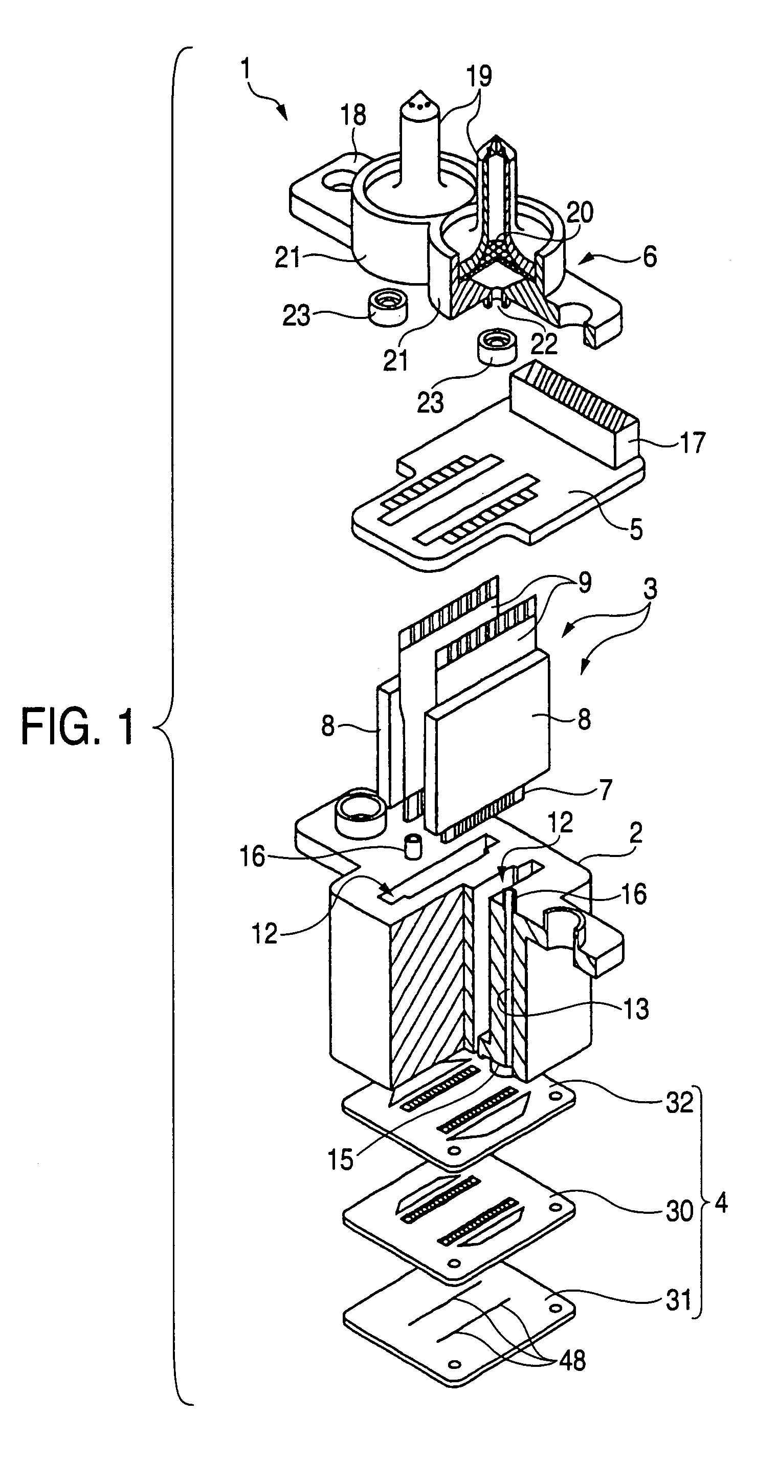
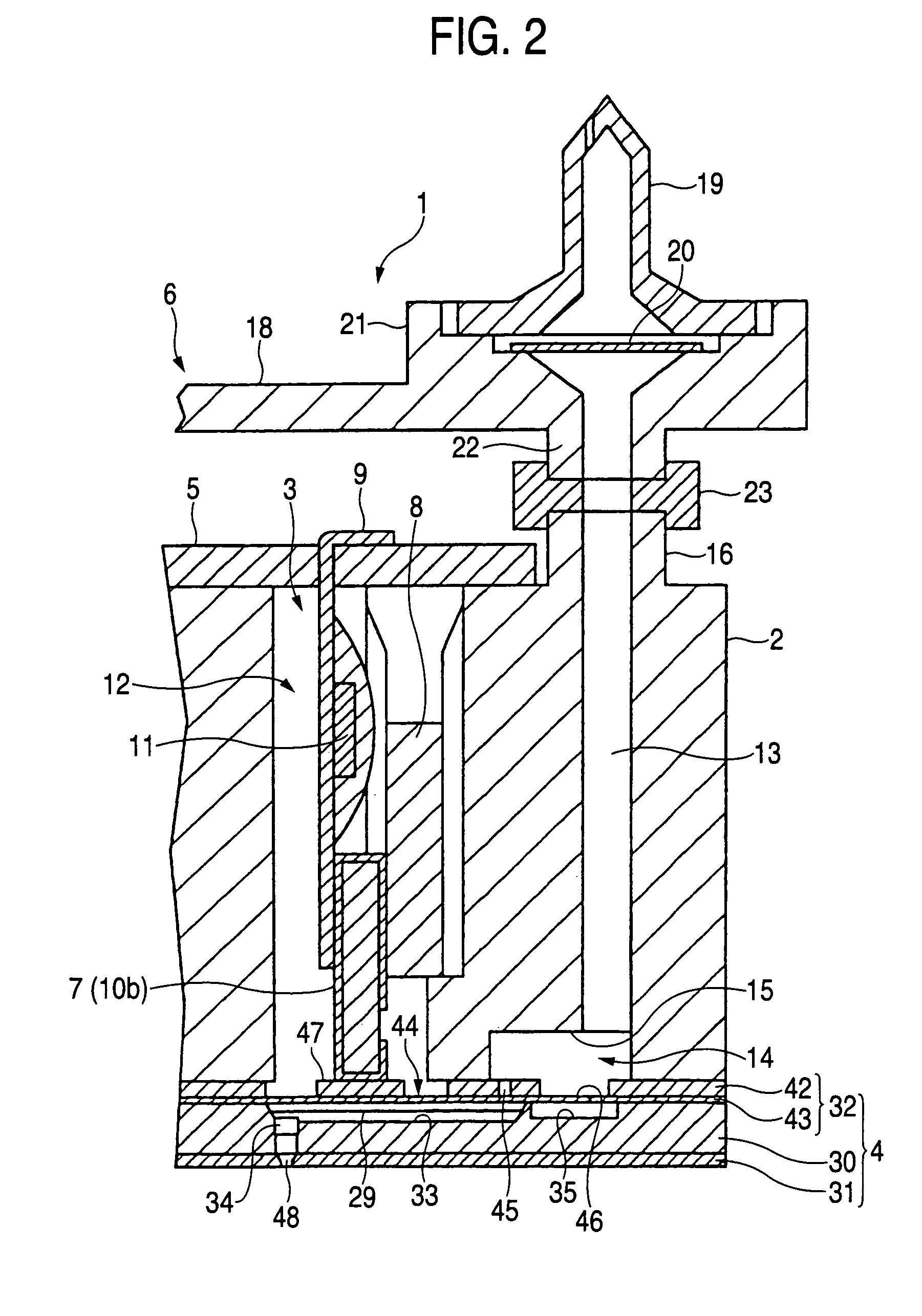
[0077]As shown in FIGS. 1 and 2, a recording head 1 is roughly constituted by a casing 2, a vibrator unit 3 contained at inside of the casing 2, a flow path unit 4 bonded to a front end face of the casing 2, a connection board 5 arranged onto a rear end face of the casing 2, a supply needle unit 6 attached to the rear end face of the casing 2.

[0078]As shown in FIGS. 3A and 3B, the vibrator unit 3 is roughly constituted by a piezoelectric vibrator group 7, a fixation plate 8 bonded with the piezoelectric vibrator group 7 and a flexible cable 9 for supplying a drive signal to the piezoelectric vibrato...


PUM

PropertyMeasurementUnit
Lengthaaaaaaaaaa
Widthaaaaaaaaaa
Widthaaaaaaaaaa

Abstract

A male die is adapted to be opposed to a first face of a metallic plate member. The male die includes a plurality of punches which are provided on the male die and arranged side by side in a first direction with a fixed pitch. A guide member is formed with a guide face which supports a side portion of the male die, at least when the punches are pressed into the plate member in a second direction, to form through holes therein.

Description

BACKGROUND OF THE INVENTION[0001]The present invention relates to a method of punching a circular or rectangular minute hole having a diameter or a long side of not greater than about 0.5 mm at a metal board by using an upper die and a lower die. The present invention also relates to a method and an apparatus for manufacturing a liquid ejection head using such a punching method.[0002]An ink jet recording head (hereinafter, referred to as “recording head”) used as an example of a liquid ejection head is provided with a plurality of series of flow paths reaching nozzle orifices from a common ink reservoir via pressure generating chambers in correspondence with the orifices. Further, the respective pressure generating chambers need to form by a fine pitch in correspondence with a recording density to meet a request of downsizing. Therefore, a wall thickness of a partition wall for partitioning contiguous ones of the pressure generating chambers is extremely thinned. Further, an ink sup...

Claims


Application Information

Patent Timeline
IPC IPC(8): B21D28/26B21D28/00B21D28/24B21D28/34B41J2/16
CPCB41J2/1603B41J2/1612B41J2/1623B41J2/1632B41J2/1634B41J2/1626Y10T29/496B41J2002/14419Y10T83/944
Inventor AKAHANE, FUJIOTAKASHIMA, NAGAMITSUHAKEDA, KAZUSHIGEUESUGI, RYOJIKUREBAYASHI, AKIHARU
Owner SEIKO EPSON CORP
Why Eureka
Try Eureka