MEMS sensor

a technology of mems sensor and diaphragm, which is applied in the field of sensors, can solve the problems of remarkably reducing the sensitivity of silicon microphones, reducing the vibrational amplitude of the diaphragm with respect to the same sound pressure, and breaking the diaphragm due to stress, so as to reduce the sensitivity of the mems sensor and suppress the effect of stress-induced diaphragm breakag

Inactive Publication Date: 2011-09-22
ROHM CO LTD
View PDF19 Cites 12 Cited by
  • Summary
  • Abstract
  • Description
  • Claims
  • Application Information

AI Technical Summary

Benefits of technology

[0018]When the main portion is supported by the two supporting portions, the maximum vibrational amplitude A2 of the diaphragm in the case where the physical quantity of the prescribed value acts on the diaphragm and the maximum stress B2 caused in the diaphragm at this time depend on the arrangement of the two supporting portions. The maximum vibrational amplitude A2 is smaller than the maximum vibrational amplitude A1 of the diaphragm in the case where the physical quantity of the prescribed value acts on the diaphragm having the structure supporting the main portion with one supporting portion. Further, the maximum stress B2 is smaller than the maximum stress B1 caused in the diaphragm in the case where the physical quantity of the prescribed value acts on the diaphragm having the structure supporting the main portion with one supporting portion. The diaphragm is hardly broken by stress as the maximum stress B2 is reduced.
[0019]If the two supporting portions are so arranged that the reduction ratio of the maximum vibrational amplitude A2 with respect to the maximum vibrational amplitude A1 exceeds the reduction ratio of the maximum stress B2 with respect to the maximum stress B1, however, the sensitivity of the MEMS sensor (vibratility of the diaphragm) is disadvantageously reduced despite the advantage of preventing breakage of the diaphragm attained by stress reduction.
[0020]Therefore, the angle formed by the two straight lines connecting the supporting portions and the center of the main portion with one another respectively is set to satisfy the relation (A2 / A1) / (B2 / B1)≧1. Thus, the two supporting portions are arranged on proper positions, and the reduction ratio of the maximum vibrational amplitude A2 with respect to the maximum vibrational amplitude A1 does not exceed the reduction ratio of the maximum stress B2 with respect to the maximum stress B1. Consequently, remarkable reduction of the sensitivity of the MEMS sensor can be prevented while breakage of the diaphragm resulting from stress can be suppressed.
[0026]According to the structure, the diaphragm vibrating due to the action of the physical quantity is provided on the substrate. The diaphragm integrally has the main portion and not less than three supporting portions. The main portion is supported by not less than three supporting portions, and arranged on the substrate in the floating state. Not less than three supporting portions extend in the direction along the surface of the substrate from different portions of the peripheral edge of the main portion respectively. Not less than three supporting portions are arranged to satisfy the relation (Ap / A1) / (Bp / B1)≧1. Thus, not less than three supporting portions are arranged on proper positions, and the reduction ratio of the maximum vibrational amplitude Ap with respect to the maximum vibrational amplitude A1 does not exceed the reduction ratio of the maximum stress Bp with respect to the maximum stress B1. Consequently, remarkable reduction of the sensitivity of the MEMS sensor can be prevented while breakage of the diaphragm resulting from stress can be suppressed.

Problems solved by technology

If the diaphragm remarkably vibrates and excessive stress is caused in the diaphragm, however, the diaphragm is broken due to the stress.
Depending on the arrangement of a plurality of supporting portions, however, the vibrational amplitude of the diaphragm with respect to the same sound pressure is extremely reduced to remarkably lower the sensitivity of the silicon microphone.

Method used


Image

  • MEMS sensor
  • MEMS sensor
  • MEMS sensor

Examples


Embodiment Construction

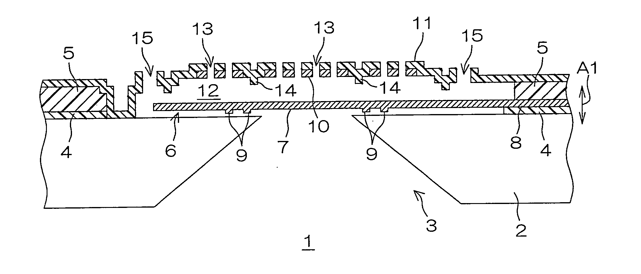
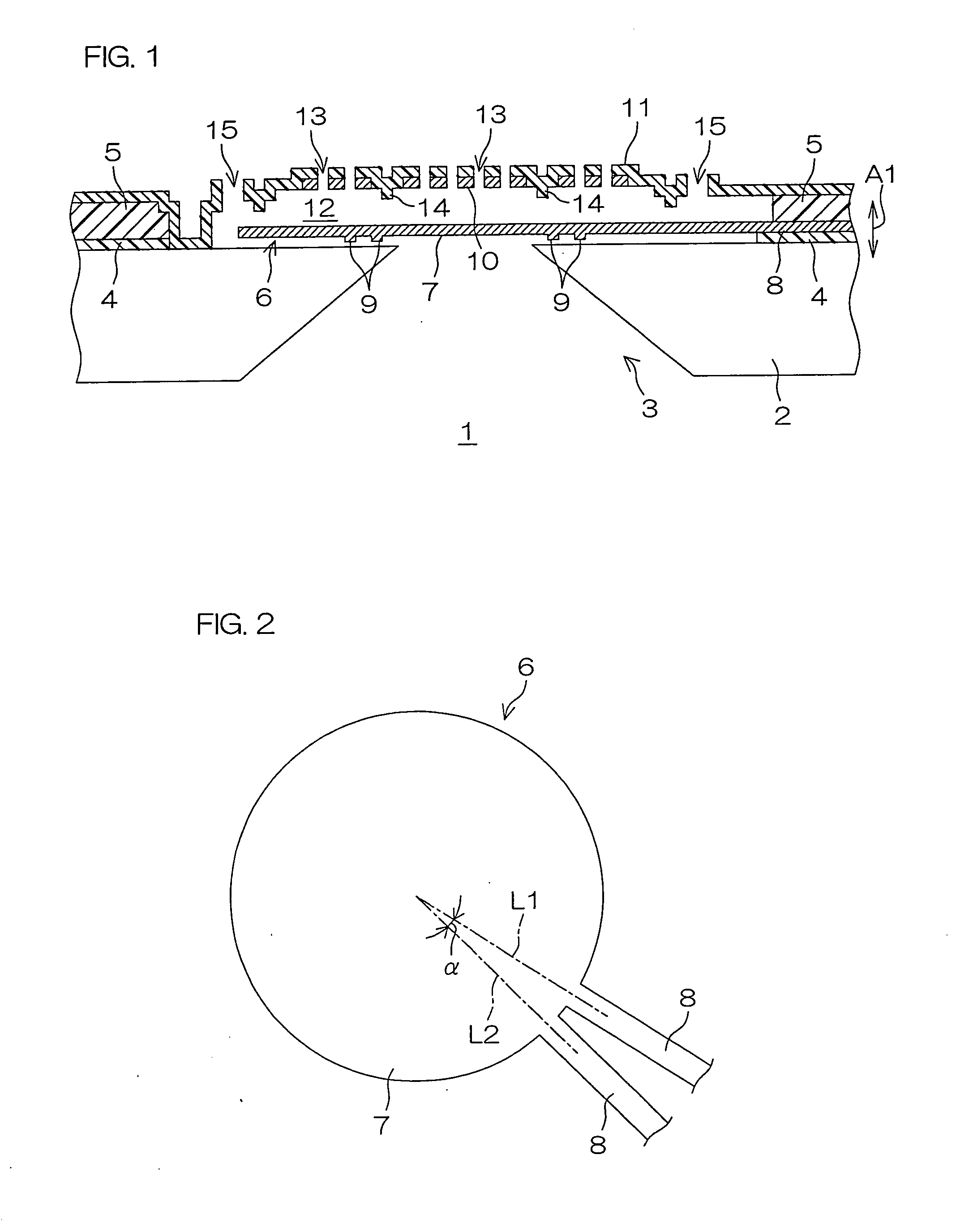
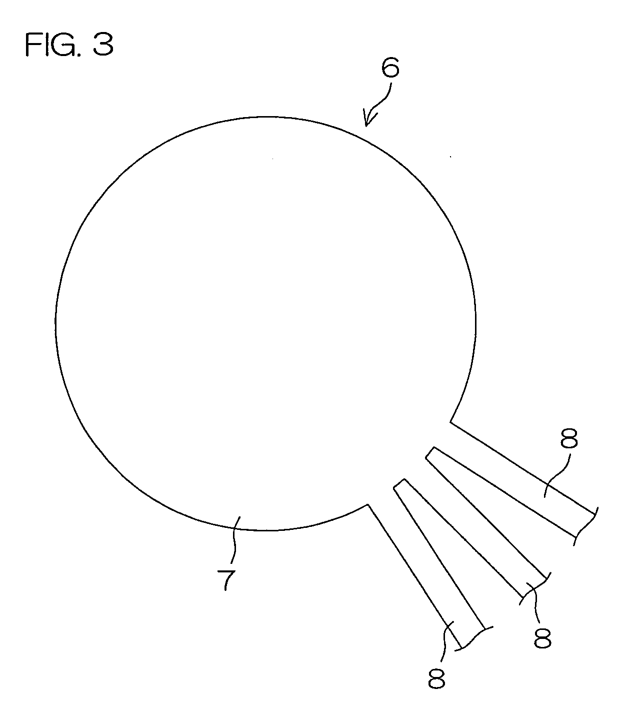
[0031]FIG. 1 is a schematic sectional view of a silicon microphone according to an embodiment of the present invention.

[0032]A silicon microphone 1 is a sensor (an MEMS sensor) manufactured by the MEMS technique. The silicon microphone 1 includes a substrate 2 made of silicon. A through-hole 3 having a trapezoidal sectional shape narrowed toward the surface (widened toward the rear surface) is formed in the central portion of the substrate 2.

[0033]A first insulating film 4 is stacked on the substrate 2. The first insulating film 4 is made of silicon oxide, for example.

[0034]A second insulating film 5 is stacked on the first insulating film 4. The second insulating film 5 is made of PSG (Phospho Silicate Glass), for example.

[0035]Portions of the first insulating film 4 and the second insulating film 5 located on the through-hole 3 and a portion (hereinafter referred to as a “through-hole peripheral portion”) of the surface (the upper surface) of the substrate 2 around the through-hol...


PUM


Abstract

The MEMS sensor according to the present invention includes a diaphragm. In the diaphragm, an angle formed by two straight lines connecting supporting portions and the center of a main portion with one another respectively is set to satisfy the relation of the following formula (1):(A2 / A1) / (B2 / B1)≧1  (1)A2: maximum vibrational amplitude of the diaphragm in a case of working a physical quantity of a prescribed value on the diaphragmA1: maximum vibrational amplitude of the diaphragm in a case of working the physical quantity on the diaphragm in an omitting structure obtained by omitting one of the supporting portions from the diaphragmB2: maximum stress caused in the diaphragm in the case of working the physical quantity on the diaphragmB1: maximum stress caused in the diaphragm in the case of working the physical quantity on the diaphragm in the omitting structure

Description

[0001]This is a Continuation of U.S. application Ser. No. 12 / 485,696, filed Jun. 16, 2009, the subject matter of which is incorporated herein by reference.BACKGROUND OF THE INVENTION[0002]1. Field of the Invention[0003]The present invention relates to various sensors (MEMS sensors) manufactured by an MEMS (Micro Electro Mechanical Systems) technique.[0004]2. Description of Related Art[0005]An MEMS sensor, having been recently loaded on a portable telephone or the like, is watched with interest. For example, a silicon microphone (an Si microphone) is a typical MEMS sensor.[0006]The silicon microphone includes a silicon substrate. A through-hole passing through the silicon substrate in the thickness direction is formed in the central portion of the silicon substrate. A diaphragm made of polysilicon is provided on the silicon substrate to be opposed to the through-hole. The diaphragm integrally has a main portion and a single supporting portion supporting the main portion. The main por...

Claims


Application Information

Patent Timeline
Patent Type & Authority Applications(United States)
IPC IPC(8): H01L29/84
CPCB81B3/007B81B2201/0235B81B2201/0257B81B2203/0118H04R19/04G01P15/125H04R7/16H04R19/005G01P15/0802
Inventor NAKATANI, GOROOKADA, MIZUHOYAMASHITA, NOBUHISA
Owner ROHM CO LTD
Why Eureka
Try Eureka