
Network switching device

a network switching and network switching technology, applied in data switching networks, digital transmission, interconnection arrangements, etc., can solve the problems of increasing power consumption in the network switching device, increasing extending so as to prevent the interruption time of the switching process from becoming excessively long, and controlling power consumption

Active Publication Date: 2011-09-22
ALAXALA NETWORKS
View PDF4 Cites 1 Cited by
  • Summary
  • Abstract
  • Description
  • Claims
  • Application Information

AI Technical Summary

Benefits of technology

[0008]An advantage of some aspects of the invention is to provide a technology that is able to control power consumption while preventing the interruption time of the switching process from becoming excessively long.
[0010]Regarding this network switching device, the determination-operation mode of the target switching block is set to a determination-operation mode that is different from the operation mode of the first switching block during the period wherein the first switching block handles the switching-determination process. Furthermore, the switching-determination process is started by the target switching block, instead of the first switching block, after completion of setting the operation mode of the target switching block. Thus, this network switching device makes it possible to changeover the determination-operation mode used for execution of the switching-determination process without setting the operation mode of the switching block in execution of the switching-determination process, nor interrupting the switching-determination process.

Problems solved by technology

On the other hand, accompanying the increased performance and the increased capacity there has also been a tendency for increased power consumption in the network switching device as well, and controlling power consumption of the network switching device has become an issue from both the perspective of system operating costs and environmental protection.
When mode is set in network switching device, problems may occur in the switching process due to the mode setting (for example, the switching process may be interrupted when the mode is being set), and there have been cases wherein this has resulted in extended interruption time of the switching process.

Method used


Image

  • Network switching device
  • Network switching device
  • Network switching device

Examples


first embodiment

A. First Embodiment

B. Second Embodiment

C. Third Embodiment

D. Variations

A. First Embodiment

Structure of a Network Switching Device

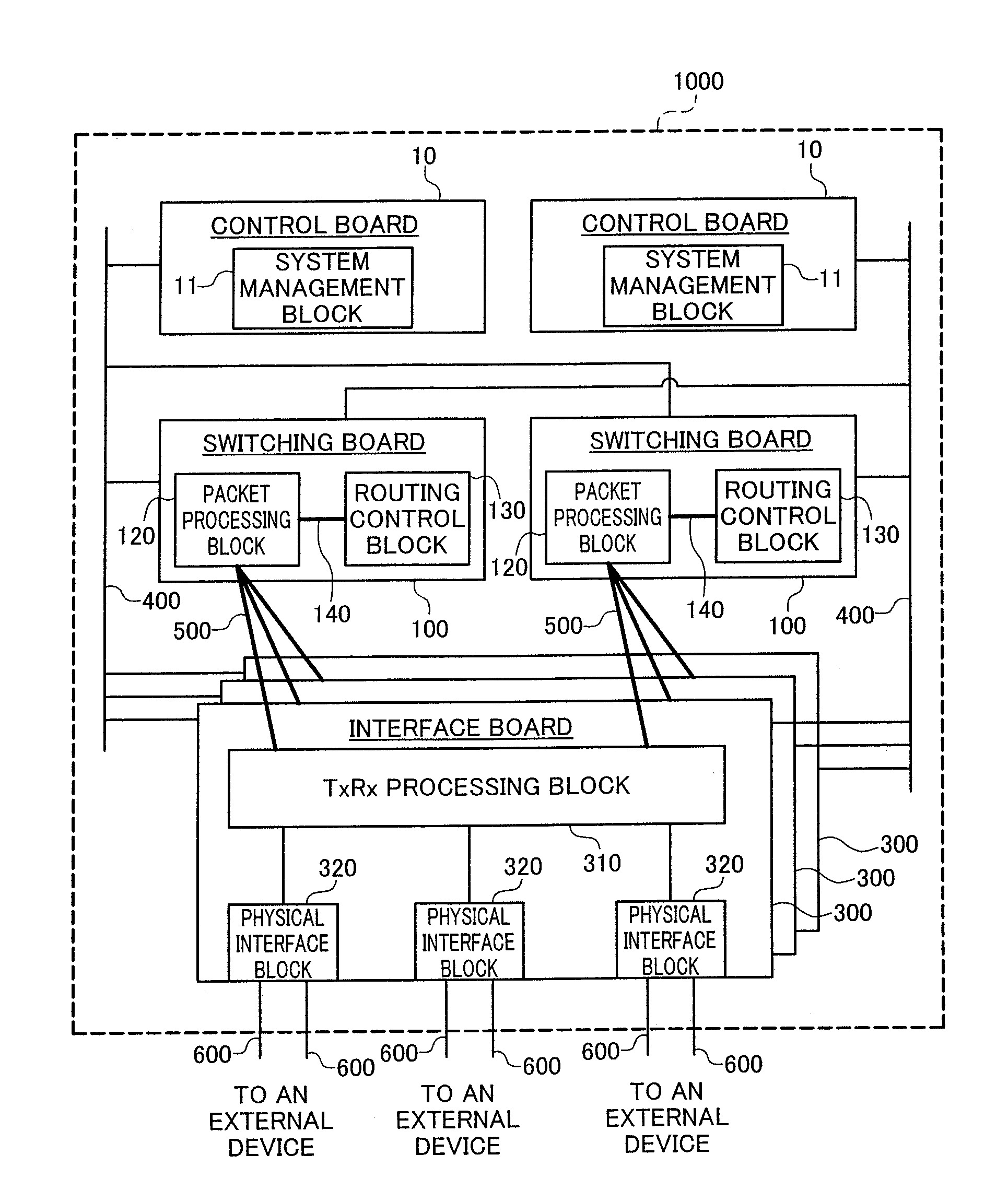
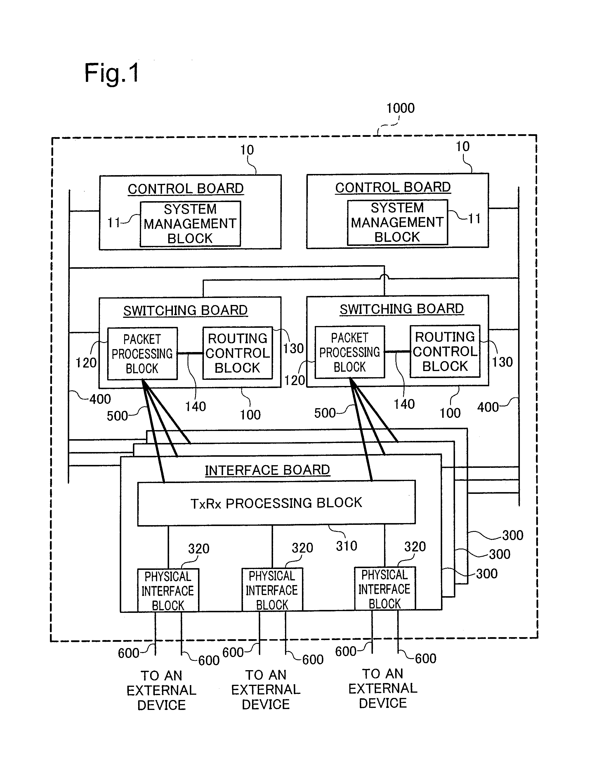
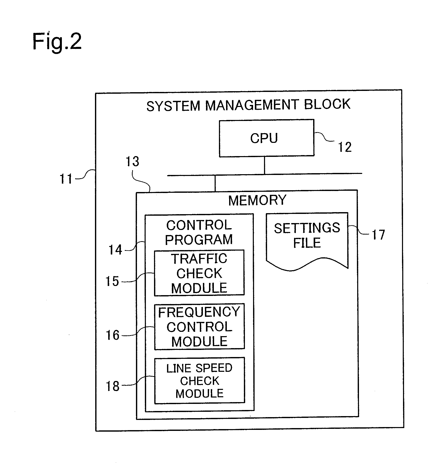
[0029]The structure of a network switching device according to the embodiment will be explained in reference to FIG. 1 through FIG. 3. FIG. 1 shows a block diagram illustrating the basic structure of a network device pertaining to the embodiment. FIG. 2 shows a block diagram of the internal structure of a system management block. FIG. 3 shows a block diagram of the structure focusing on an interface board and a switching board.

[0030]As is shown in FIG. 1, the network switching device 1000 pertaining to the embodiment includes, primarily, a control board 10, a switching board 100, and an interface board 300. The control board 10 includes a system management block 11. The control board 10 is connected, so as to be able to communicate, through a control bus 400 to the switching board 100 and the interface board 300. The system management block 11 of the contr...

second embodiment

B. Second Embodiment

[0090]FIG. 16 through FIG. 20 are schematic diagrams illustrating an overview of a operation mode management process in a network switching device 1001 according to a second embodiment. The structure of this network switching device 1001 is the same as the structure of the network switching device 1000 according to the first embodiment, described above, with the addition of a third switching board 100c. This third switching board 100c, as with the other boards 100a and 100b, is connected to a control board 10 and an interface board 300. Moreover, the structure of the third switching board 100c is the same as the other boards 100a and 100b. Note that in FIG. 16 through FIG. 20, only the three switching boards 100a through 100c, a representative interface board 300 and the first control board 10a are shown as the constituent elements of the network switching device 1001, and the other constituent elements thereof are omitted in the drawings. Moreover, in the explan...

third embodiment

C. Third Embodiment

[0103]FIG. 21 through FIG. 25 are schematic diagrams illustrating an overview of the operation mode management process in a network switching device 1002 according to a third embodiment. The difference with the network switching device 1001 according to the second embodiment, shown in FIG. 16 to FIG. 20 is the point that one of the three switching boards 100a through 100c is used as a “spare board.” In this embodiment, the total number of the active board is one, and the total number of the standby board is one. In the example illustrated in FIG. 21, the first switching board 100a functions as the active board, the second switching board 100b functions as the standby board, and the third switching board 100c is used as the spare board. The “spare board” preferably has the power supply thereto turned off under normal conditions. Moreover, the operation mode of the spare board may be set to a operation mode with less power consumption than that of the “standby board...


PUM


Abstract

Network switching arrangements including: setting an operation mode of a target switching block to a operation mode that is different from an operation mode of a first switching block while the first switching block is handling a switching process, the target switching block being one switching block selected from second switching blocks; performing a switchover process including starting the switching process using the target switching block instead of the first switching block, after completion of setting the operation mode of the target switching block; and copying the switching information held by the first switching block to the target switching block, prior to starting the switching process using the target switching block, after completion of setting the operation mode of the target switching block.

Description

CROSS REFERENCE TO RELATED APPLICATION[0001]This is a continuation of U.S. application Ser. No. 11 / 487,992, filed Jul. 18, 2006. This application relates to and claims priority from Japanese Patent Application No. 2006-049955, filed on Feb. 27, 2006. The entirety of the contents and subject matter of all of the above is incorporated herein by reference.BACKGROUND[0002]1. Technical Field[0003]The present invention relates to network switching devices, and in particular to reducing power consumption in network switching devices.[0004]2. Description of the Related Art[0005]A network switching device, including a switch and a router, is a critical device in a network system. In recent years there have been remarkable increases in performance and capacity of the network switching device accompanying an increase in data traffic sent through the network and accompanying an increase in size of the network. On the other hand, accompanying the increased performance and the increased capacity ...

Claims


Application Information

Patent Timeline
Patent Type & Authority Applications(United States)
IPC IPC(8): H04L12/56H04L45/58H04L45/586
CPCH04L49/40H04L49/25H04L49/552
Inventor SHINOHARA, MASAYUKIMATSUYAMA, NOBUHITOMURANAKA, TAKAYUKIKIMURA, ISAOAKAHANE, SHINICHI
Owner ALAXALA NETWORKS
Learn More