Footwear Cleat

a technology of traction element and cleat, which is applied in the direction of fastenings, uppers, bootlegs, etc., can solve the problems of losing the resiliency of the cleat, and achieve the effect of more energy to deform and faster deformation return

Inactive Publication Date: 2011-09-29
CURLEY JOHN J
View PDF13 Cites 17 Cited by
  • Summary
  • Abstract
  • Description
  • Claims
  • Application Information

AI Technical Summary

Benefits of technology

[0010]The instant invention comprises a dynamic golf cleat having a plurality of composite dynamic traction elements; the elements preferably assume an angle with respect to the plane of the shoe sole, to allow room for deflection toward the shoe sole under pressure load. Each dynamic traction element is preferably formed of an elastomeric material including, but not limited to thermoplastic urethane. A series of embedded thin tensile members are disposed to be oriented and integrally formed within each flexible traction element, and are preferably molded within each dynamic traction element. Each individual tensile member is centrally located within each corresponding dynamic traction element. This orientation allows for the creation within each dynamic traction element of distinct upper and lower surface areas. As such, these sections of the dynamic traction elements possess facing surfaces which are joined by the thin tensile member sections.
[0011]According to one embodiment of the instant invention, two elastomeric sections separated by a thin tensile member define a dynamic traction element, and within these dynamic traction elements are areas defined as stress concentration zones, or stress lenses. These stress lenses are preferably comprised of ridges and / or grooves oriented and disposed to be integrally formed within each dynamic traction elements. The ridges or grooves are designed to concentrate or focus the stresses caused by deformation from broad areas of the elastomeric dynamic traction elements into smaller concentrated areas of the elastomeric elements. As a result, this concentration of stresses, such as compression stress or tensile stress require more energy to deform the material, than if the stresses were more broadly dispersed within its molecular structure. Therefore, the faster deformation return in this embodiment may be attributed to the embedded and integrally molded tensile member surface conforming to the curved sections of a plurality of traction teeth and which is disposed to be substantially bendable and able to conform to straight teeth sections.

Problems solved by technology

The result on a golf cleat is that over time, more and more intermolecular bonds will break, thereby will lose a cleat's resiliency to quickly return to a cleat's original position, and instead will remain in a compressed set.

Method used


Image

  • Footwear Cleat
  • Footwear Cleat
  • Footwear Cleat

Examples


second embodiment

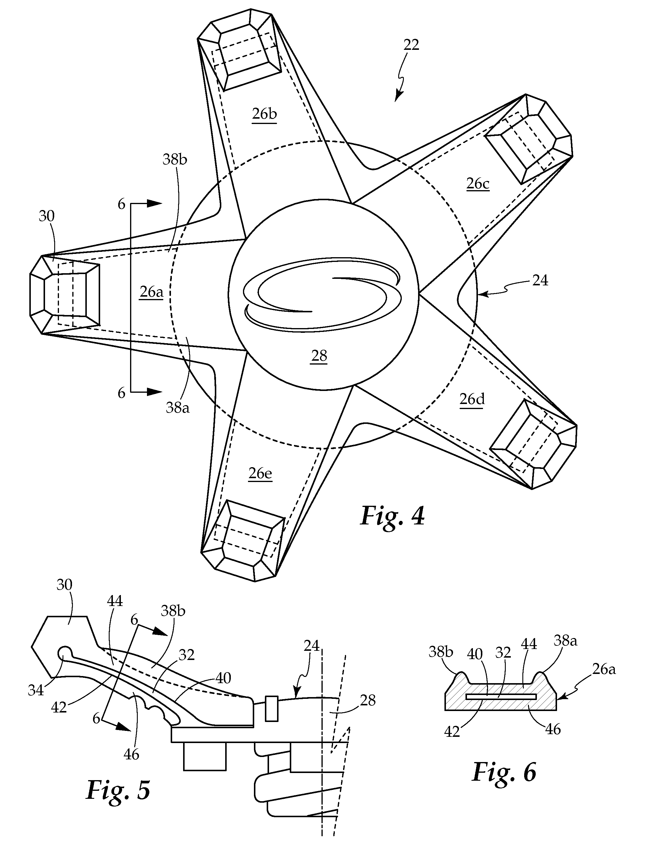
[0057]FIG. 8 illustrates a second embodiment and is a top view of the embedded tensile members 32 and their threaded base 48. The wings that extend away from the center are the integral molded tensile members 50a through 50e. Shown on the surface of the tensile members are the integrally molded holes 52a through 52e that create the mechanical bonds that exist between the tensile members and their associated dynamic traction members. These mechanical bonds will assist the chemical bonds that will occur between the urethane and the nylon material on their contacting upper and lower surfaces in maintaining structural integrity.

third embodiment

[0058]FIG. 9 illustrates a third embodiment and is a top view of the embedded tensile members and their threaded base 54. The wings that extend away from the center are the integral molded tensile members 56a through 56e. Shown on the ends of the tensile members are the integrally molded ridges 34a through 34e along with the integrally molded holes 52a through 52e both of which will create the mechanical bonds that exist between the tensile members and their associated dynamic traction members. These mechanical bonds will assist the chemical bonds that will occur between the urethane and the nylon material on their contacting upper and lower surfaces in maintaining structural integrity.

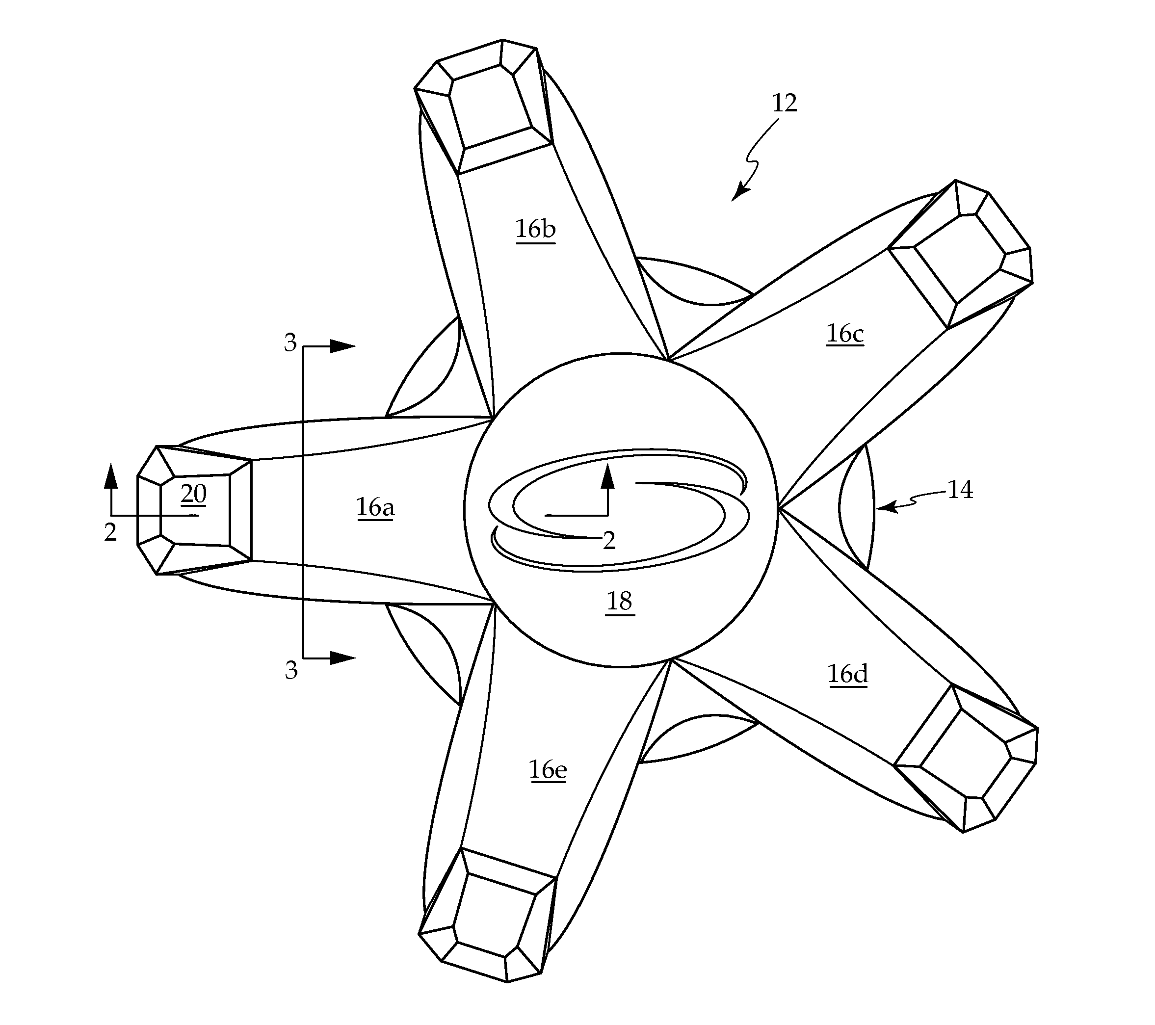
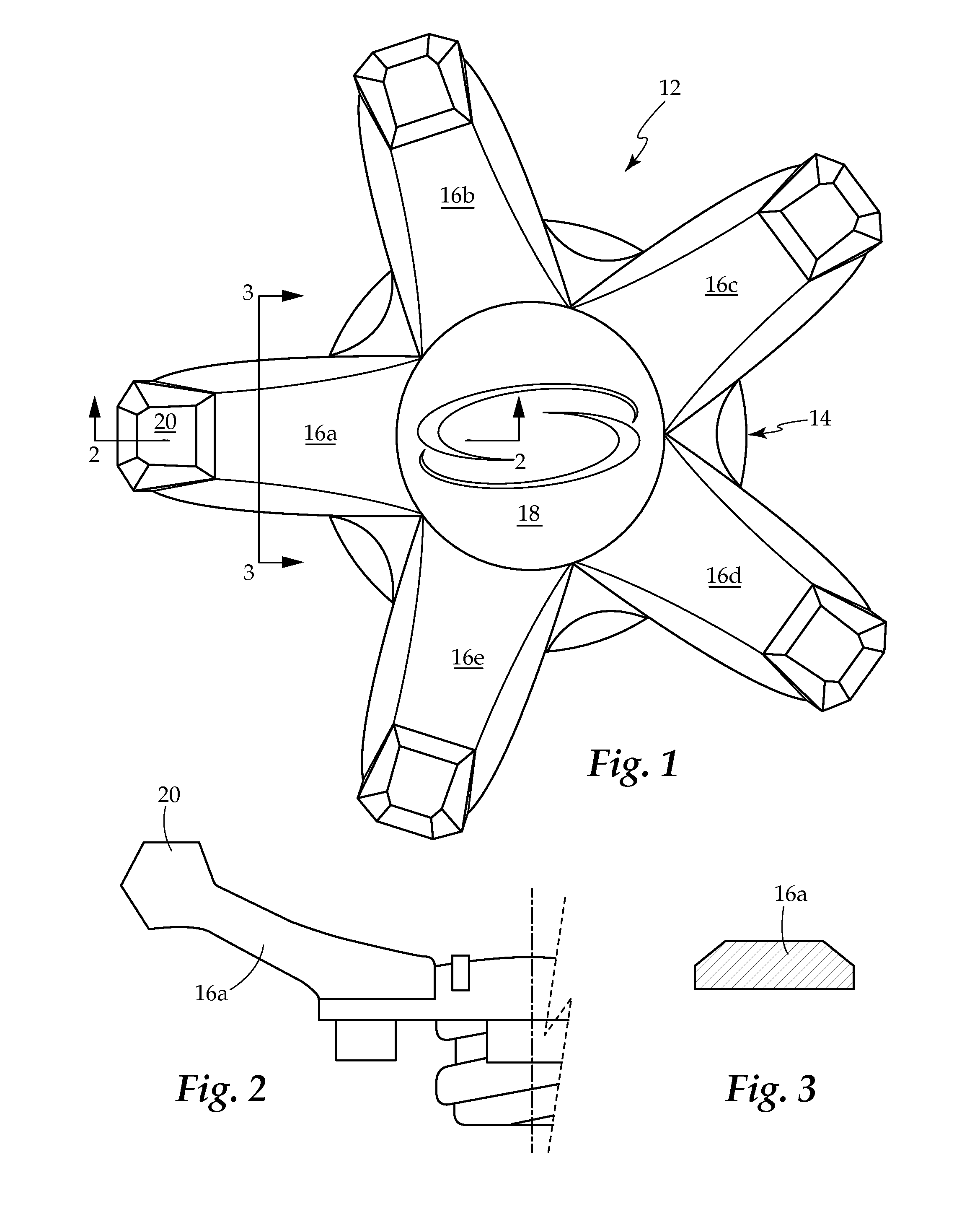
[0059]FIG. 10A is a sectioned, longitudinal side elevation view of a dynamic traction element taken along section line 2-2 and shows the simple non-composite dynamic traction element 16a with its traction tooth area 20 along with a central hub portion 14 having a convex central wear area 18, the same ...


PUM


Abstract

A dynamic golf cleat having a plurality of composite dynamic traction elements, the wherein the elements preferably assume an angle with respect to the plane of the shoe sole, to allow room for deflection toward the shoe sole under load. The dynamic traction element is preferably formed of an elastomeric material such as thermoplastic urethane. A hub portion having a threaded attachment means is preferably oriented perpendicular to the plane of the shoe sole. Extending outwardly in a radial manner from the hub portion is a plurality of embedded thin tensile members oriented to be integrally formed within each flexible traction element. Each individual tensile member is centrally located within each dynamic traction element creating a distinct upper surface area and a lower surface area, within each dynamic traction element. Said sections of the dynamic traction elements have facing surfaces joined by a thin tensile member sections. These thin tensile member sections are molded integral with the two flexible traction element, an upper surface area and a lower surface area.

Description

CROSS REFERENCE TO RELATED APPLICATION[0001]This application claims the benefit of and takes priority under 35 U.S.C. §119 to U.S. Patent Application No. 61 / 279,704 filed on Oct. 26, 2009.BACKGROUND OF THE INVENTION[0002]1. Field of the Invention[0003]This invention relates to a dynamic traction element, and more particularly to a dynamic traction element construction wherein a flexible elastomeric traction arm element is designed and configured to yield an improved dynamic traction element providing for a faster rate of deformation return following compression.[0004]2. Description of the Related Prior Art[0005]Prior dynamic traction element constructions include dynamic traction elements having pivoted or articulated sections joined together in a central hub area; these flexible traction elements are composed of a singular material, typically a resilient thermoplastic urethane dynamic element configuration.[0006]There are three forces or stresses that may act on a material, all of ...

Claims


Application Information

Patent Timeline
Patent Type & Authority Applications(United States)
IPC IPC(8): A43C15/00
CPCA43C15/162
Inventor CURLEY, JOHN J.
Owner CURLEY JOHN J
Why Eureka
Try Eureka