Seam welding method and machine therefor

a welding method and machine technology, applied in the field of seam welding method as well as, can solve the problems of sputtering (spattering of the melted workpiece) and the nest between the thinnest workpiece and the thinnest workpiece, and achieve the effect of reducing the risk of sputtering

Inactive Publication Date: 2011-09-29
HONDA MOTOR CO LTD
View PDF3 Cites 24 Cited by
  • Summary
  • Abstract
  • Description
  • Claims
  • Application Information

AI Technical Summary

Benefits of technology

[0013]In broad terms, an object of the present invention is to provide a seam welding method that can cause a nugget to grow sufficiently bet

Problems solved by technology

When the layered body is seam-welded with the thinnest workpiece being disposed on an outermost side of the layered body, the nugget, which resides between the thinnest workpiece and another workpiece adjacent to the thinnest workpiece, may not grow sufficiently.
It is conjectured that t

Method used


Image

  • Seam welding method and machine therefor
  • Seam welding method and machine therefor
  • Seam welding method and machine therefor

Examples


Embodiment Construction

[0057]With reference to the accompanying drawings, a detailed description of exemplary embodiments of a seam welding method according to the present invention will be described below, in conjunction with a seam welding machine for carrying out the seam welding method.

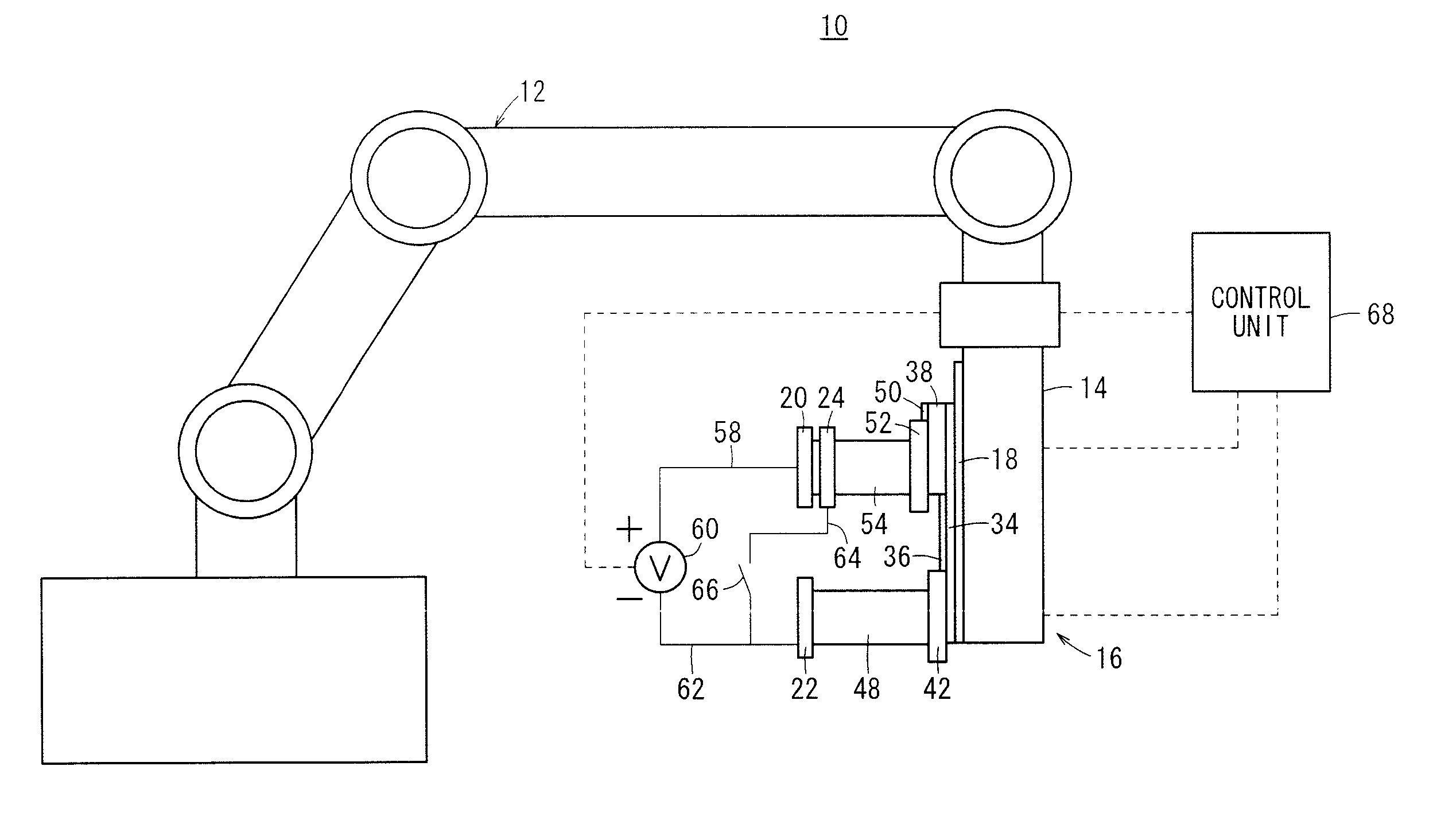
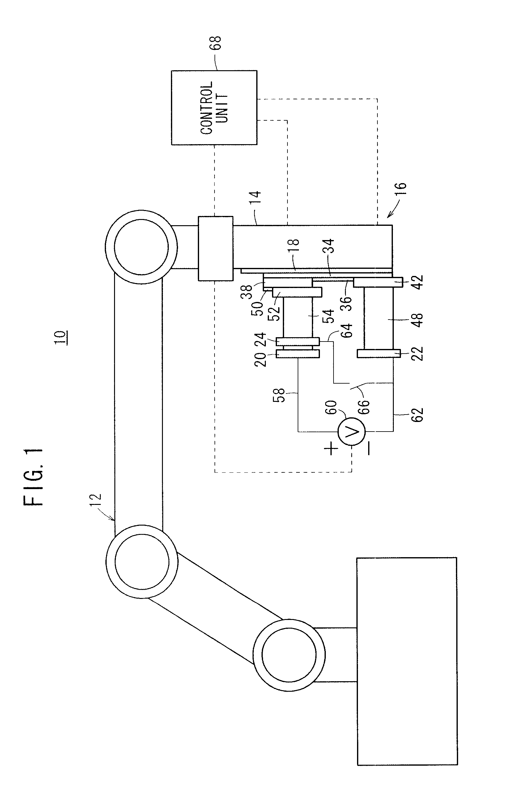
[0058]FIG. 1 is a schematic side elevational view showing a seam welding machine 10 in its entirety according to a first exemplary embodiment. The seam welding machine 10 includes a multi-joint robot 12 and a seam welder 16, which is supported on a distal arm 14 of the multi-joint robot 12. The components of the seam welding machine 10, which is made up by a combination of the multi-joint robot 12 and the seam welder 16, are well-known, as disclosed in Japanese Laid-Open Patent Publication No. 2007-167896 and Japanese Utility Model Registration No. 3124033. Accordingly, detailed explanations concerning the arrangement of such components will not be provided herein.

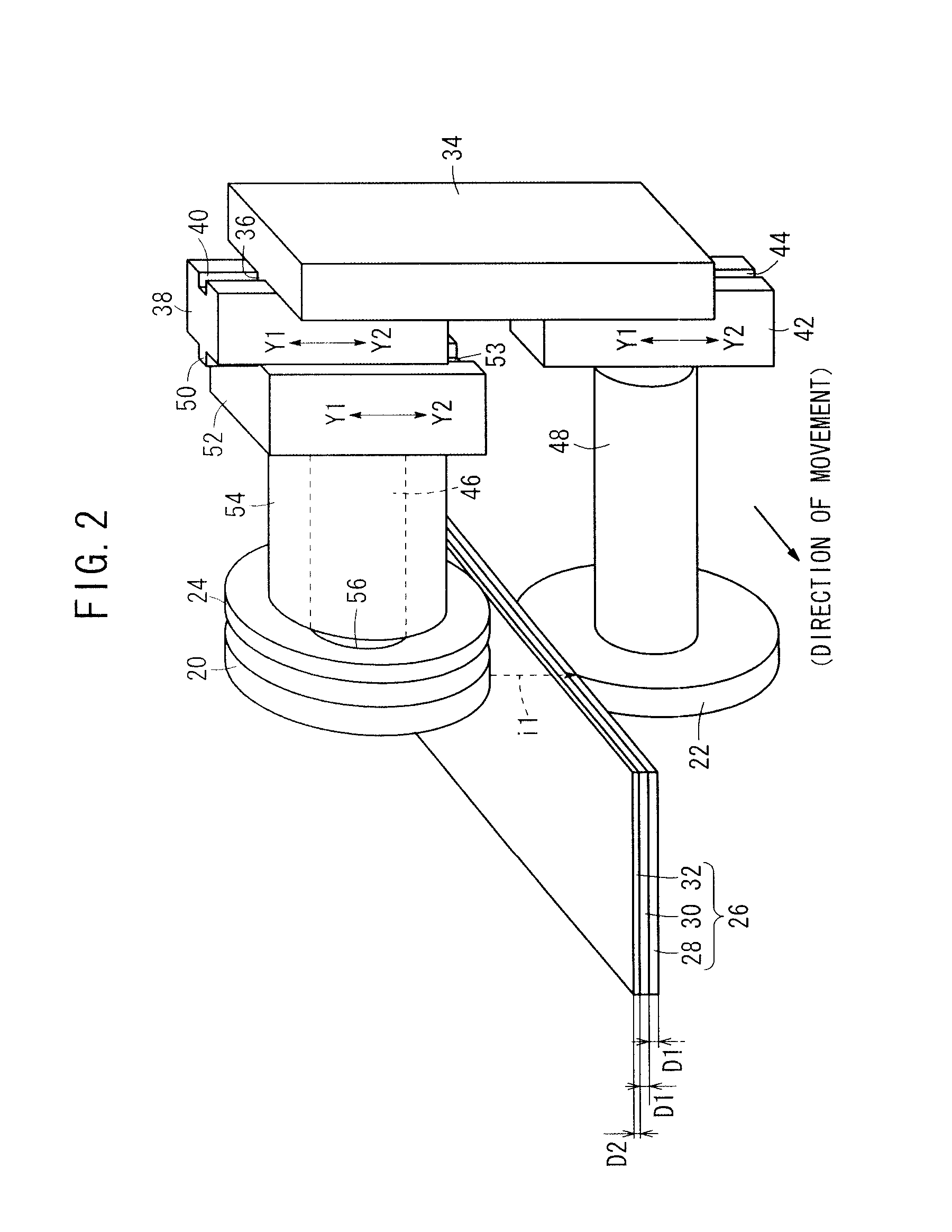
[0059]As shown in FIG. 2 (which is a partially sectioned...


PUM

PropertyMeasurementUnit
Polarityaaaaaaaaaa
Currentaaaaaaaaaa

Abstract

A seam welding machine includes a first roller electrode and a second roller electrode that hold a layered body formed by layering a plurality of workpieces. The first roller electrode is in contact with a thinnest workpiece, which is disposed on an outermost side of the layered body. The seam welding machine has a current-branching electrode held in contact with the thinnest workpiece, and which is charged with a polarity opposite to that of the first roller electrode. Accordingly, when an electric current is applied between the first roller electrode and the second roller electrode that hold the layered body, a branch electric current is applied from the first roller electrode to the current-branching electrode, or a branch electric current is applied from the current-branching electrode to the first roller electrode.

Description

CROSS-REFERENCE TO RELATED APPLICATION[0001]This application is based upon and claims the benefit of priority from Japanese Patent Application No. 2010-066004 filed on Mar. 23, 2010, of which the contents are incorporated herein by reference.BACKGROUND OF THE INVENTION[0002]1. Field of the Invention[0003]The present invention relates to a seam welding method as well as to a machine therefor, for seam welding a layered body produced by layering three or more workpieces, with a thinnest workpiece having the smallest thickness being disposed on an outermost side thereof.[0004]2. Description of the Related Art[0005]Seam welding is widely known as a method for bonding metal plates. As disclosed in Japanese Laid-Open Patent Publication No. 2007-167896 and Japanese Utility Model Registration No. 3124033, during seam-welding, after layered metal plates (which form a layered body) are held between a pair of roller electrodes, an electric current is applied between the roller electrodes. In o...

Claims


Application Information

Patent Timeline
IPC IPC(8): B23K11/08
CPCB23K11/002B23K2203/04B23K11/061B23K2103/04
Inventor KANEKO, MITSUGUHASEGAWA, EISAKUGOTO, AKIRA
Owner HONDA MOTOR CO LTD
Why Eureka
Try Eureka