Semi-levered landing gear and associated method

a landing gear and semi-levered technology, applied in the field of landing gear, can solve the problems of increasing the cost and complexity of landing gear, affecting the efficiency of landing gear,

Active Publication Date: 2011-09-29
THE BOEING CO
View PDF13 Cites 38 Cited by
  • Summary
  • Abstract
  • Description
  • Claims
  • Application Information

AI Technical Summary

Benefits of technology

[0008]In accordance with embodiments of the present disclosure, a semi-levered landing gear is provided that is configured to position a truck beam in a toes-up attitude during takeoff and then reposition the truck beam in a

Problems solved by technology

While a semi-levered landing gear having a locking hydraulic strut is suitable for some aircraft, the landing gear of other aircraft may not have sufficient clearance or room for the hydraulic strut to be positioned between the shock strut and the truck beam in

Method used


Image

  • Semi-levered landing gear and associated method
  • Semi-levered landing gear and associated method
  • Semi-levered landing gear and associated method

Examples


Embodiment Construction

[0033]The present disclosure now will be described more fully hereinafter with reference to the accompanying drawings, in which some, but not all embodiments of the inventions are shown. Indeed, these embodiments may take many different forms and should not be construed as limited to that set forth herein; rather, these embodiments are provided so that this disclosure will satisfy applicable legal requirements. Like numbers refer to like elements throughout.

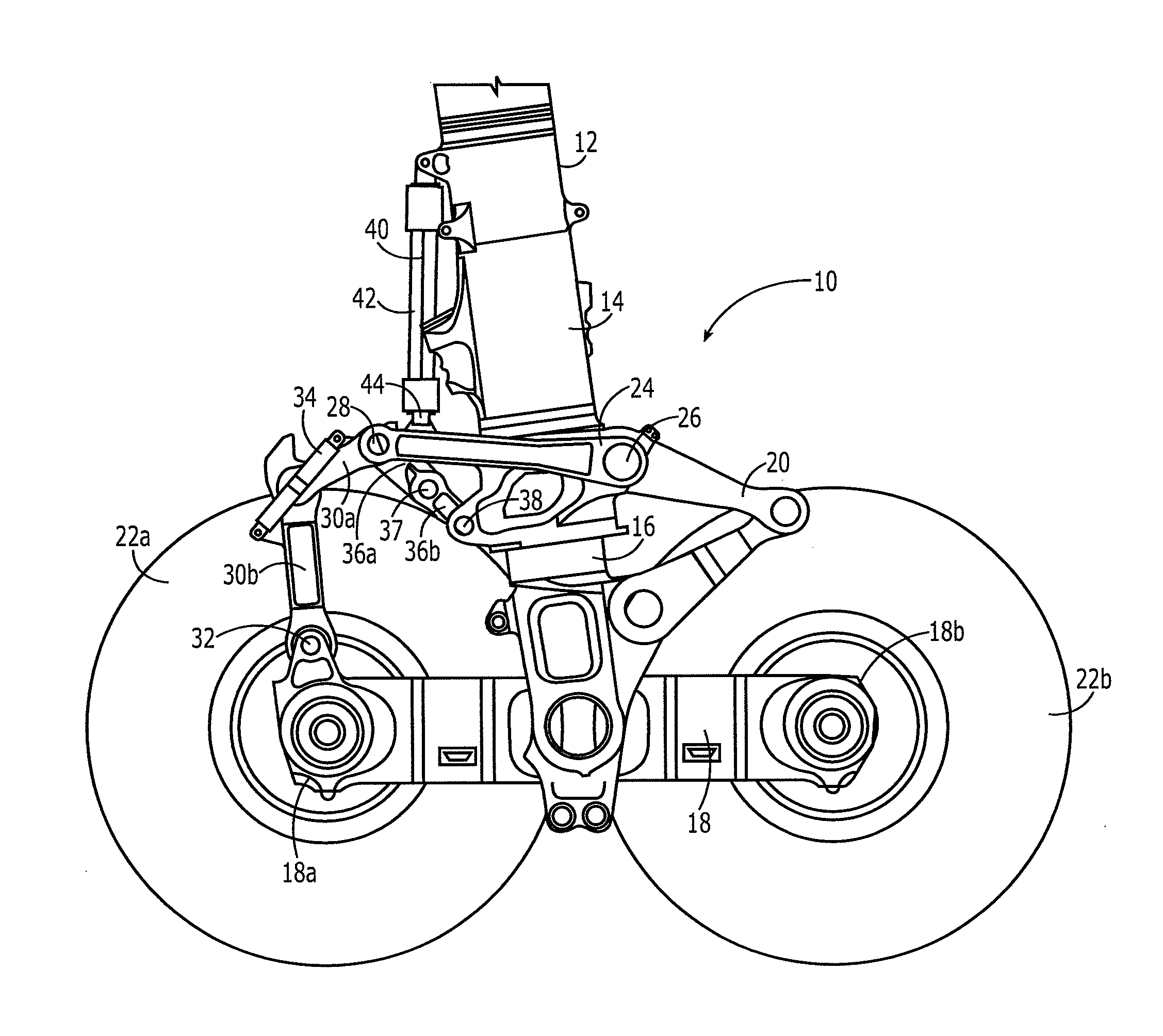
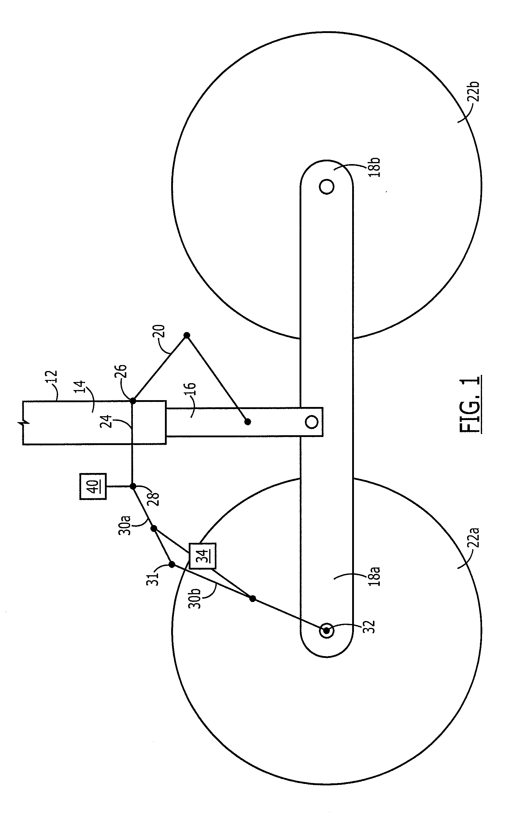
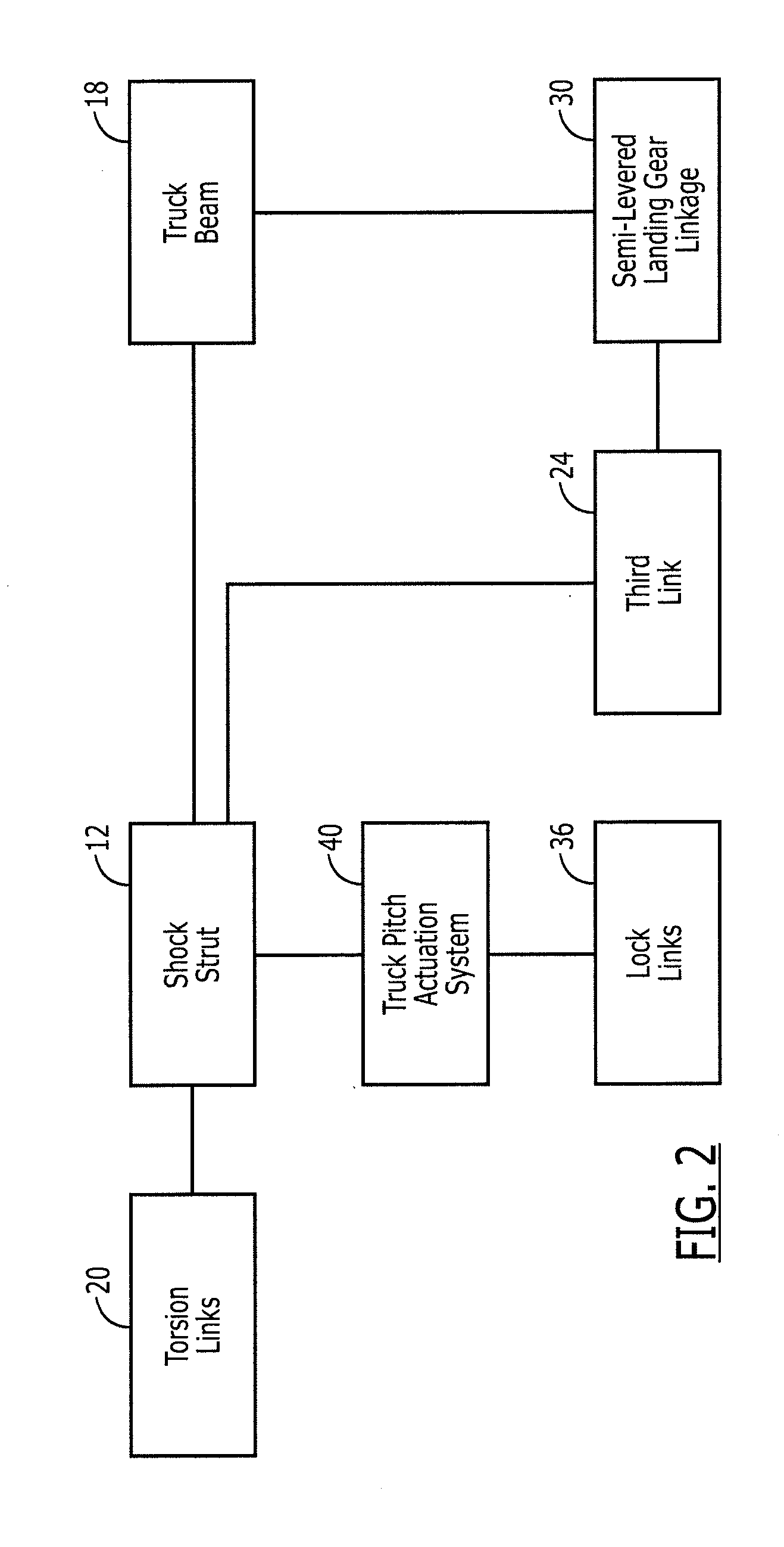
[0034]Referring now to FIGS. 1 and 2, a schematic representation and a functional block diagram of a semi-levered landing gear 10 in accordance with one embodiment are respectively depicted. As shown, the semi-levered landing gear includes a shock strut 12 extending downwardly from the fuselage of an aircraft or other air vehicle. As described below, the shock strut generally includes an outer cylinder 14 and an inner cylinder 16. The semi-levered landing gear may include torsion links 20 extending between the inner and outer cyl...


PUM


Abstract

A semi-levered landing gear is provided that includes a shock strut, a truck beam pivotally connected to the shock strut and a semi-levered landing gear mechanism including at least three links configured to angularly orient the truck beam and a truck pitch actuation system operatively connected to at least one of the three links. The landing gear mechanism may be configured to cooperate with an extension of a shock strut by positioning the truck pitch actuator in a retracted position, thereby positioning a forward end of the truck beam in a raised position relative to the aft end of the truck beam. The landing gear mechanism may also be configured to cooperate with a retraction of the shock strut into the wheel well by extending the truck pitch actuator to position a forward end of the truck beam in a lower position relative to the aft end of the truck beam.

Description

TECHNOLOGICAL FIELD[0001]Embodiments of the present disclosure relate generally to landing gear and, more particularly, to a semi-levered landing gear and an associated method of positioning the truck beam of the landing gear.BACKGROUND[0002]An airplane includes landing gear to facilitate takeoff, landing and taxi. The landing gear of some aircraft includes a shock strut that is pivotally attached to a truck beam at a distal or lower end thereof. The truck beam includes two or more axles upon which tires are mounted. In this regard, the truck beam may include a forward axle positioned forward of the shock strut and an aft axle positioned aft of the shock strut. Upon takeoff, an airplane having a conventional landing gear with forward and aft axles will pivot about the pin that attaches the truck beam to the shock strut such that all of the landing gear tires have an equal load distribution.[0003]In order to provide additional ground clearance for rotation of the aircraft during take...

Claims


Application Information

Patent Timeline
IPC IPC(8): B64C25/10
CPCB64C25/34B64C25/04B64C25/20B64C2025/008
Inventor MELLOR, MITCHELL L.LONG, MICHAEL A.ODELL, RICHARD B.
Owner THE BOEING CO
Why Eureka
Try Eureka