Joint

a joint and joint technology, applied in the field of joint, can solve the problems of increased fuel burn, eroded edge of the panel, difficult and time-consuming process, etc., and achieve the effect of reducing the bending stress in the land

Inactive Publication Date: 2011-09-29
AIRBUS OPERATIONS LTD
View PDF9 Cites 26 Cited by
  • Summary
  • Abstract
  • Description
  • Claims
  • Application Information

AI Technical Summary

Benefits of technology

[0012]The cover and structure may have opposing panel edges substantially perpendicular to their outer surfaces. This en

Problems solved by technology

Outside of this range, the step created in the outer surface across the joint leads to drag and increased fuel burn, and also issues with erosion of the edge of the panel 2.
However, as the butt-straps 3 are typically fitted in various strips (nominally around 30 cm in length) across the whole span of the wing, this process can be difficult and time consuming.
This adds further complexity to the process

Method used


Image

  • Joint
  • Joint
  • Joint

Examples


Embodiment Construction

)

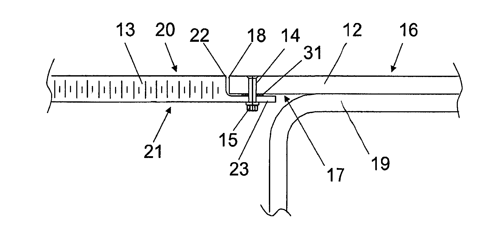
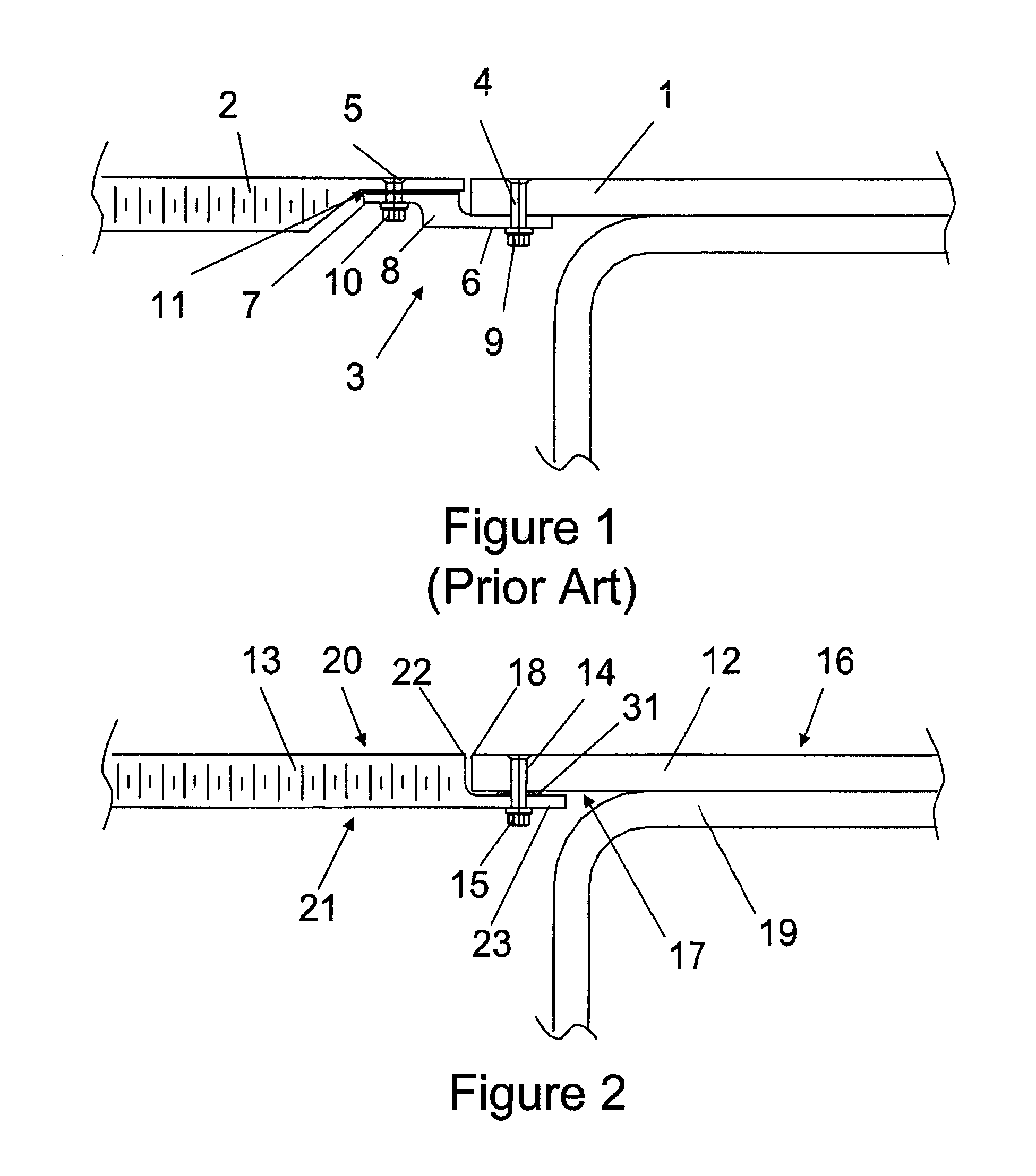
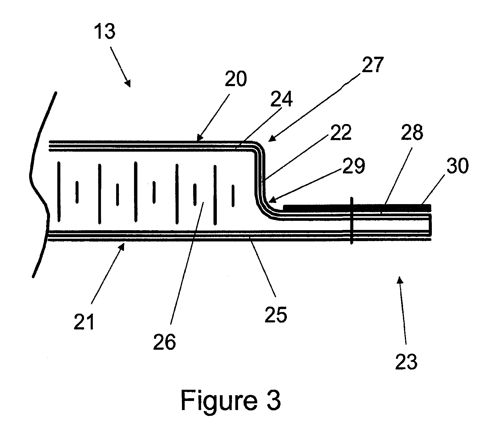
[0020]An aircraft wing box upper cover 12 is attached to a trailing edge shroud panel 13 with a bolt 14 and nut 15. The cover 12 has an outer aerodynamic surface 16, an inner surface 17, and a trailing edge 18. The cover 12 forms part of an aircraft wing box structure of conventional type, and is fixed to the upper flange of the rear spar 19, as shown in FIG. 2. The panel 13 extends from the trailing edge 18 of the wing box structure to a trailing edge flap device (not shown), so as to complete the aerofoil profile of the wing. The panel 13 has an outer aerodynamic surface 20, an inner surface 21, a leading edge 22, and a land 23. The land 23 extends forwardly from the panel leading edge 22 over the inner surface 17 of the cover 12.

[0021]To achieve a smooth aerodynamic surface, the outer surface 16 of the cover 12 and the outer surface 20 of the panel 13 must be aligned with each other within a strict tolerance range. Outside of this range, the step created in the outer surface acr...


PUM

PropertyMeasurementUnit
Thicknessaaaaaaaaaa

Abstract

A joint between an aircraft wing box cover and a leading/trailing edge structure, the cover and the structure having flush aerodynamic outer surfaces, wherein the structure has an integrally formed land that extends over an inner surface of the cover, and the land of the structure is fastened to the cover. Also a method of forming the joint.

Description

FIELD OF THE INVENTION[0001]The present invention relates to a joint between an aircraft wing box cover and a leading / trailing edge structure. The invention also relates to a method of forming such a joint.BACKGROUND OF THE INVENTION[0002]Conventional aircraft wings comprise a wing box with front and rear spars. Upper and lower wing covers are attached to the spars and extend between them to form the upper and lower boundaries of the wing box. Leading and trailing edge structures, such as trailing edge shroud panels or D-nose covers, are typically attached to the upper and lower covers with butt-straps. FIG. 1 illustrates a conventional butt-strap arrangement.[0003]An upper wing cover 1 is attached to a trailing edge shroud panel 2 with a butt-strap 3, a pair of bolts 4, 5 and nuts 9, 10. The butt-strap 3 comprises upper and lower horizontal portions 6, 7 which are joined by a vertical portion 8. The lower portion 6 engages with the inner surface of the cover 1, while the upper port...

Claims


Application Information

Patent Timeline
IPC IPC(8): B64C3/00B64C1/00B23P11/00B23P17/00
CPCB64C3/28Y10T29/49771Y10T29/49826
Inventor STEWART, DAVID MARK
Owner AIRBUS OPERATIONS LTD
Why Eureka
Try Eureka