Communication installation support tool for tunnels and subways

a technology for installing support and tunnels, which is applied to cables, special-purpose vessels, transportation and packaging, etc., can solve the problems of labor and human resources, inconvenience and time-consuming, and achieve the effect of reducing damage to surrounding structures

Inactive Publication Date: 2011-09-29
US HLDG
View PDF13 Cites 12 Cited by
  • Summary
  • Abstract
  • Description
  • Claims
  • Application Information

AI Technical Summary

Benefits of technology

[0006]According to a more specific object of the invention, the installation support tool includes an adjustable arm, a base, a positioning structure and a control system. The adjustable arm is extendable from a minimum to maximum length to allow installation in various sizes of tunnels and subways. A positioning structure is attached to the base and the adjustable arm and allows for the adjustable arm to be rotated through and held at a range of positions up to 80 degrees relative to the vertical position in either horizontal direction. The positioning structure also includes a slider structure so that the attached end of the adjustable arm may be moved along the horizontal direction to reach either side of the tunnel or subway. The control system is connected to the positioning structure and allows control of such rotation of the adjustable arm. The base is mounted to a railcar or other movable support structure to allow movement and positioning along the axis of the tunnel or subway.
[0007]The adjustable arm includes inner and outer sleeve portions which allow for the extension of the arm for positioning of the cable and other communications networks close to the final mounting position in the tunnel and subway. The arm can be extended manually. The arm is locked in place by use of locking pins and a series of holes in the inner and outer sleeve portions of the adjustable arm. The arm may also be extended by hydraulic or electric means. The adjustable arm supports the weight of the cable and other communications networks during the installation process. The adjustable arm includes a cable control head at the free end of such arm. The cable control head is comprised of several sheaves to safely control the cable without risk of damage to the cable while the cable is feeding from a cable spool through the adjustable arm to the workers. The cable control head includes a release hinge safety feature to minimize damage to surrounding structures should the control head come into contact with another structure. The control head includes a hinge at its base and a shear pin which together allow the control head to swing up to 180 degrees away from a point of impact.
[0008]The positioning structure allows for the adjustable arm to be rotated through and held at a range of positions up to 80 degrees relative to the vertical position in either horizontal direction. The adjustable arm is fixed onto the positioning structure and is rotated via a gearbox mechanism. The positioning structure is mounted on a sled mounted on casters so that the attached end of the adjustable arm may travel horizontally between two tracks on a base frame to reach either side of the tunnel or subway. The tracks encapsulate the casters to prohibit any derailment or detachment of the positioning arm from the track base frame. The tracks include a series of holes to allow locking pins to be placed to prevent movement of the positioning structure once located in the desired position.
[0009]The control system is connected to the positioning structure and allows control of such rotation of the adjustable arm. The control system includes a control panel display and a series of light sensors located on the positioning structure and the adjustable arm. The light sensors act as a stopping mechanism to prohibit the adjustable arm from rotating beyond its maximum limit of rotation by eliminating power to the electric drive once the beams are broken. The light sensors are infrared to prohibit the safety device from inadvertently being activated by another light source or obstacle.

Problems solved by technology

Furthermore, the installation of communications equipment and systems in such tunnels involves working with long, unsupported lengths of cabling and other communications systems.
This can be inconvenient and time consuming, because the manual labor and human resources required to perform such installation operations are cumbersome and excessive.

Method used


Image

  • Communication installation support tool for tunnels and subways
  • Communication installation support tool for tunnels and subways
  • Communication installation support tool for tunnels and subways

Examples


Embodiment Construction

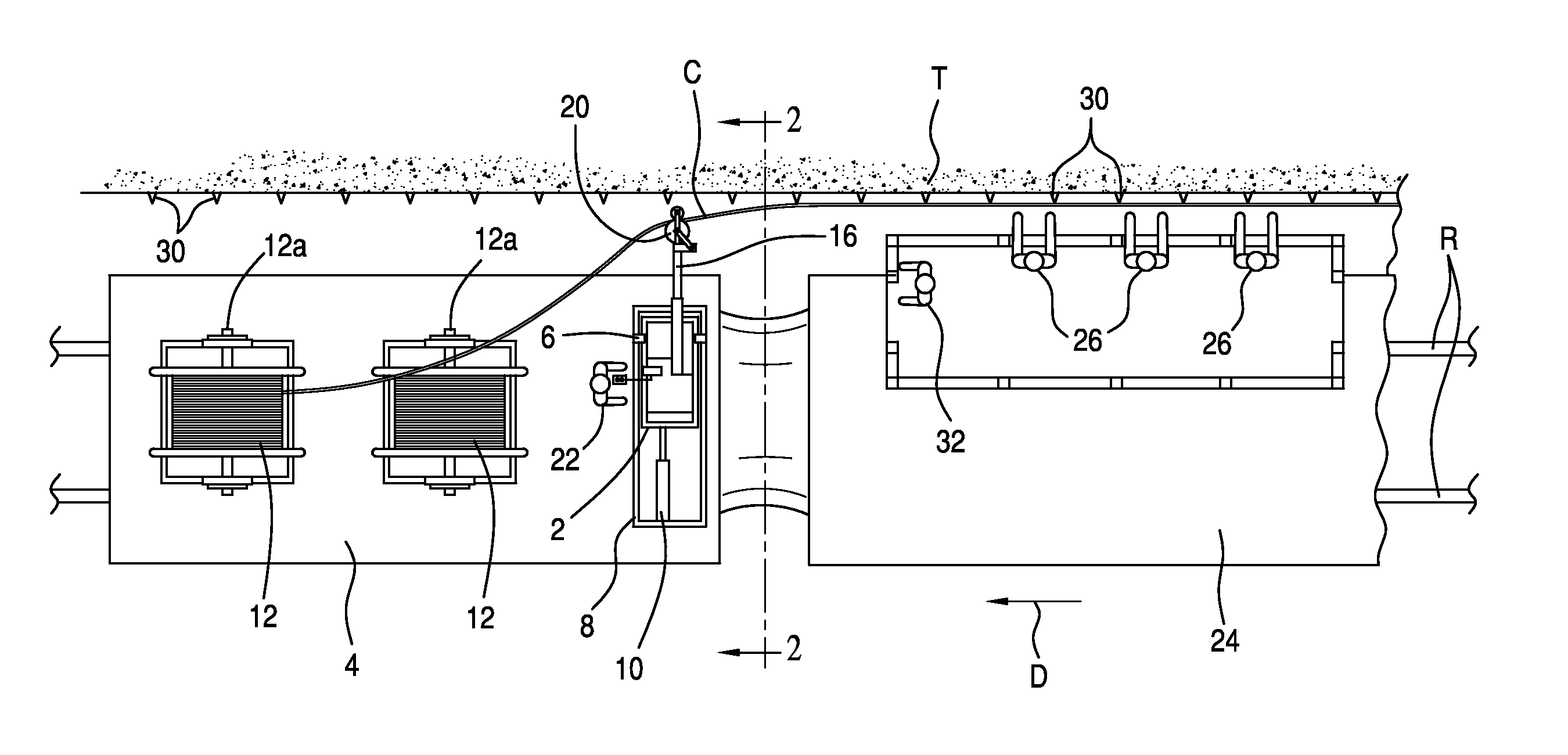
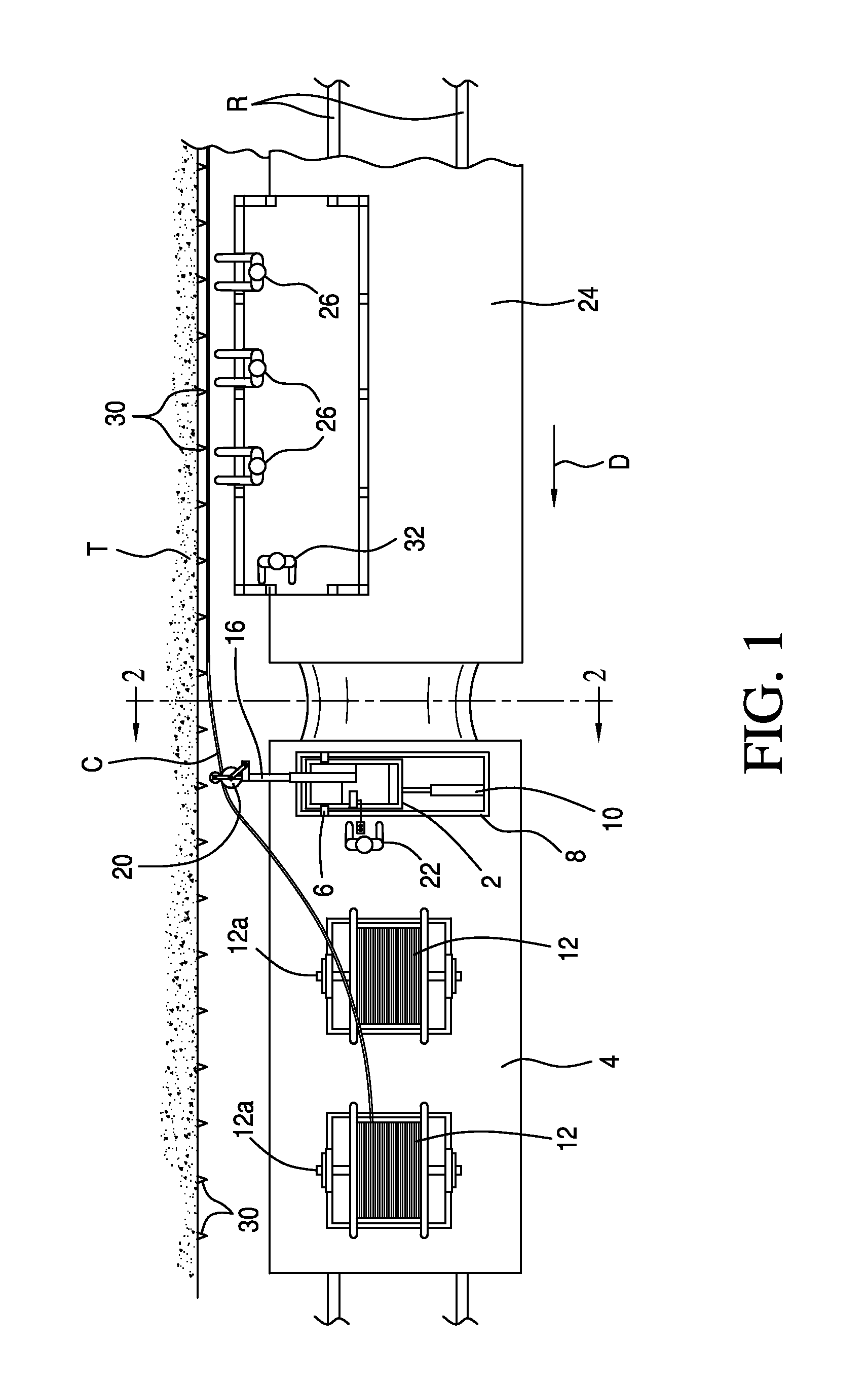
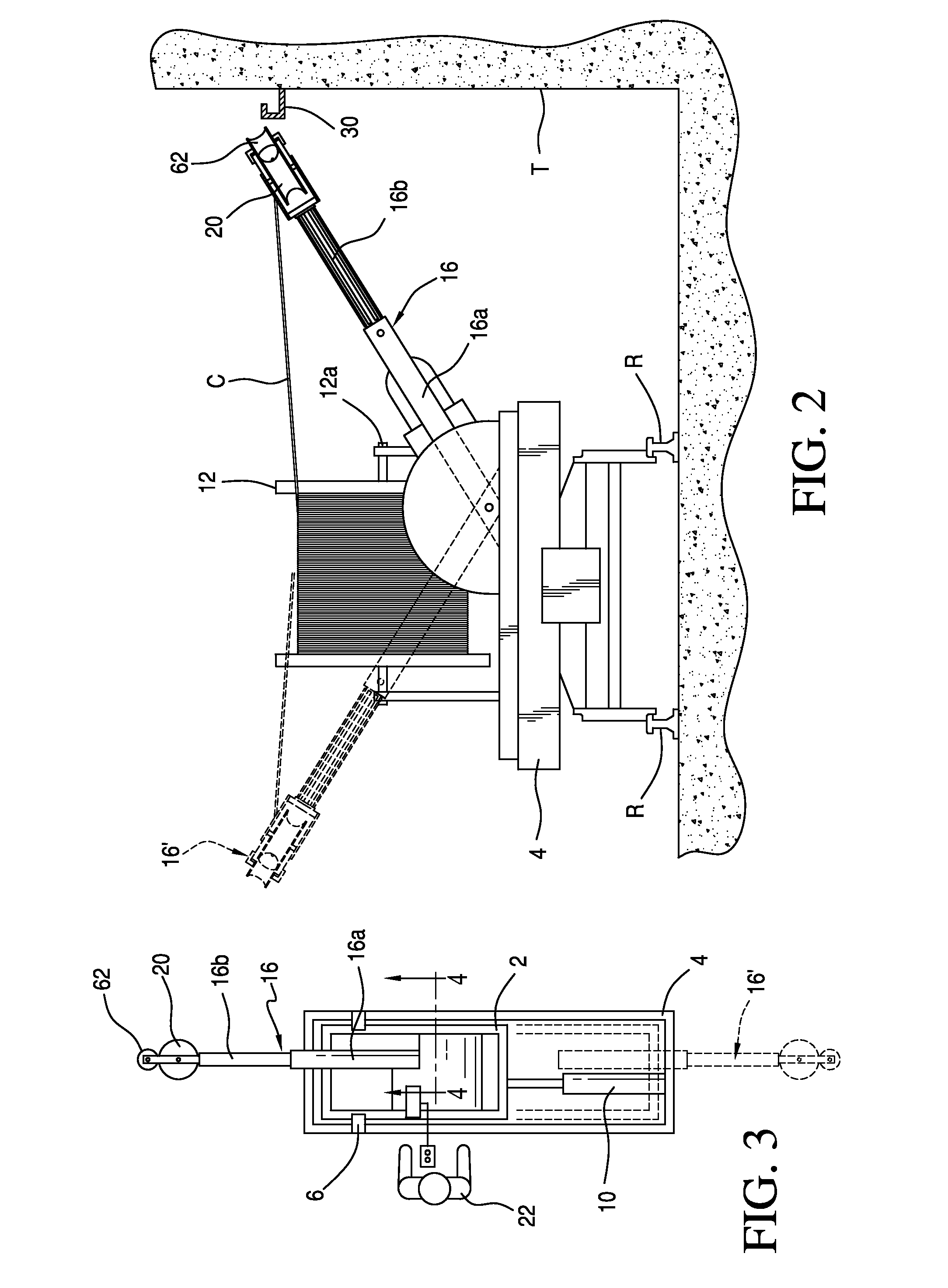
[0024]Referring first more particularly to FIGS. 1-3, the cable installing apparatus of the present invention includes a base member 2 that is supported by a first flatbed unit 4 of railway rolling stock for travel longitudinally through a tunnel T along a pair of fixed support rails R in the direction indicated by the arrow D. The base member 2 comprises a sled that is supported by slide elements 6 on a fixed rectangular frame 8 for lateral displacement transversely of the flatbed unit, as controlled by first piston and cylinder hydraulic motor means 10. Rotatably mounted on the horizontal upper surface of the flatbed unit adjacent the base member 2 are a plurality of cable supply reels 12. In the illustrated embodiment, the cable supply reels rotate about parallel horizontal axes 12a that extend normal to the direction of travel D of the flatbed unit 4. The cables C are flexible communication cables, power cables, or the like.

[0025]An adjustable-length cable guide arm 16 is pivota...


PUM


Abstract

Apparatus for installing communication and power cables in tunnels includes a base member adapted for longitudinal transport through a tunnel on a railroad flatbed that rotatably supports a cable supply reel. A cable guide arm is connected at one end with the base member for pivotal displacement about a horizontal pivot axis parallel with the base member longitudinal axis, and a cable guide pulley is connected with the other end of the guide arm for guiding a cable supplied by the reel to a desired point of installation on the tunnel wall. A length-adjusting arrangement adjusts the length of the guide arm to correspond with the width of the tunnel, and an angle-adjusting arrangement adjusts the angle of the guide arm relative to the horizontal surface of the base member. The base member is mounted on a sled for lateral displacement transversely of the flatbed.

Description

BACKGROUND OF THE INVENTION[0001]1. Field of the Invention[0002]The present invention relates generally to installation support tooling for cabling and other communications systems and equipment in subways and tunnels.[0003]2. Brief Description of the Prior Art[0004]Work on installation of cabling and other communications networks in tunnels and subways typically requires workers to access portions of the tunnels and subways that are out of their immediate reach. Furthermore, the installation of communications equipment and systems in such tunnels involves working with long, unsupported lengths of cabling and other communications systems. In addition, in order to work safely around rail lines having an electrified third rail in such tunnels and subways, workers normally must shut of the electricity being supplied to such third rail. This can be inconvenient and time consuming, because the manual labor and human resources required to perform such installation operations are cumbersom...

Claims


Application Information

Patent Timeline
Patent Type & Authority Applications(United States)
IPC IPC(8): H02G1/08
CPCB60M1/28
Inventor WARREN, SAMWONDER, ALLEN
Owner US HLDG
Why Eureka
Try Eureka