
Coupling Element

Inactive Publication Date: 2011-09-29
VIMAR SOC COMERCIAL
View PDF3 Cites 4 Cited by
  • Summary
  • Abstract
  • Description
  • Claims
  • Application Information

AI Technical Summary

Benefits of technology

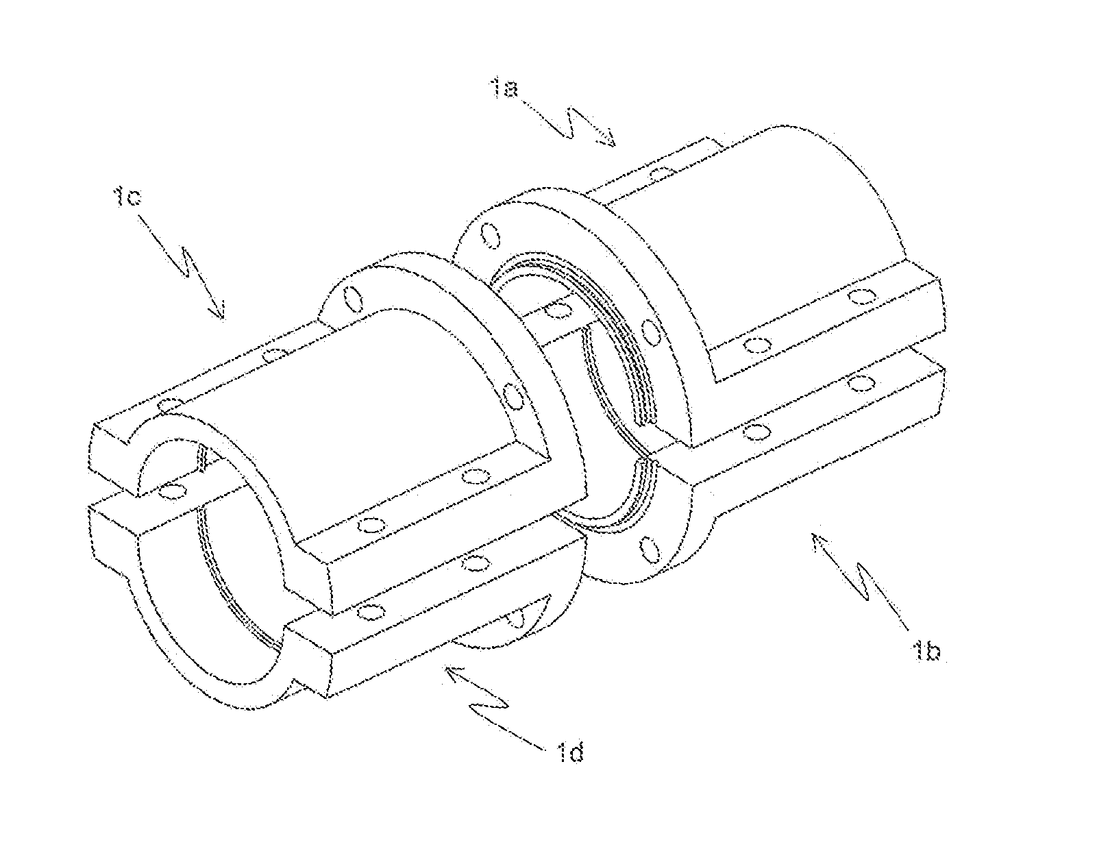
[0014]The present invention refers to a joint assembly for pipe ends comprised by two couplings, wherein a first coupling is located at one end of a first pipe and a second coupling is located at one end of a second pipe. Each coupling has means to secure the appropriate sealing between the inner portion thereof and the outer surface of the pipe. In addition, both couplings have sealing elements, which allow secure joining and coupling their faces, thus generating a watertight seal that prevents the fluid conveyed by the pipes from leaking.
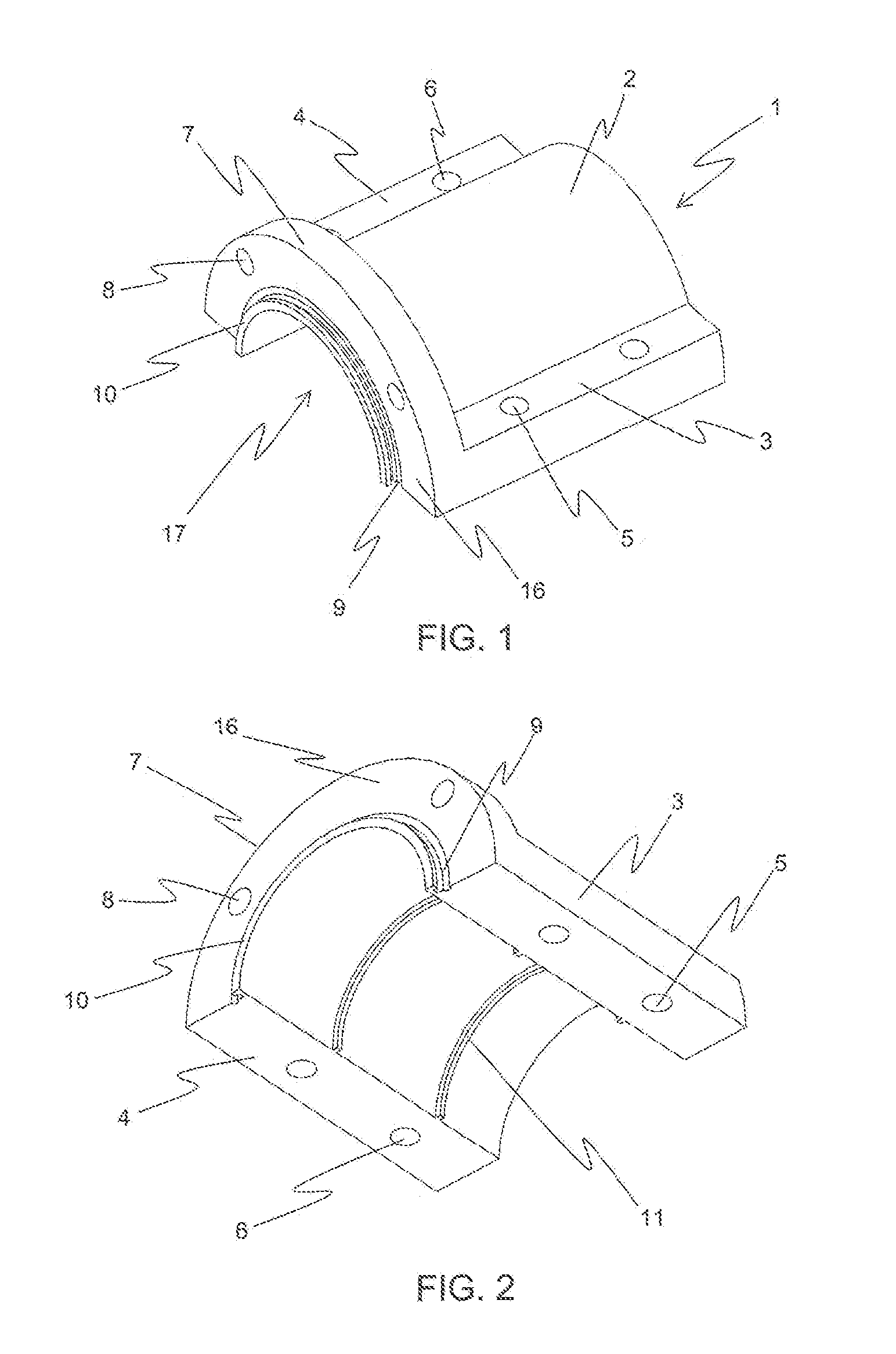
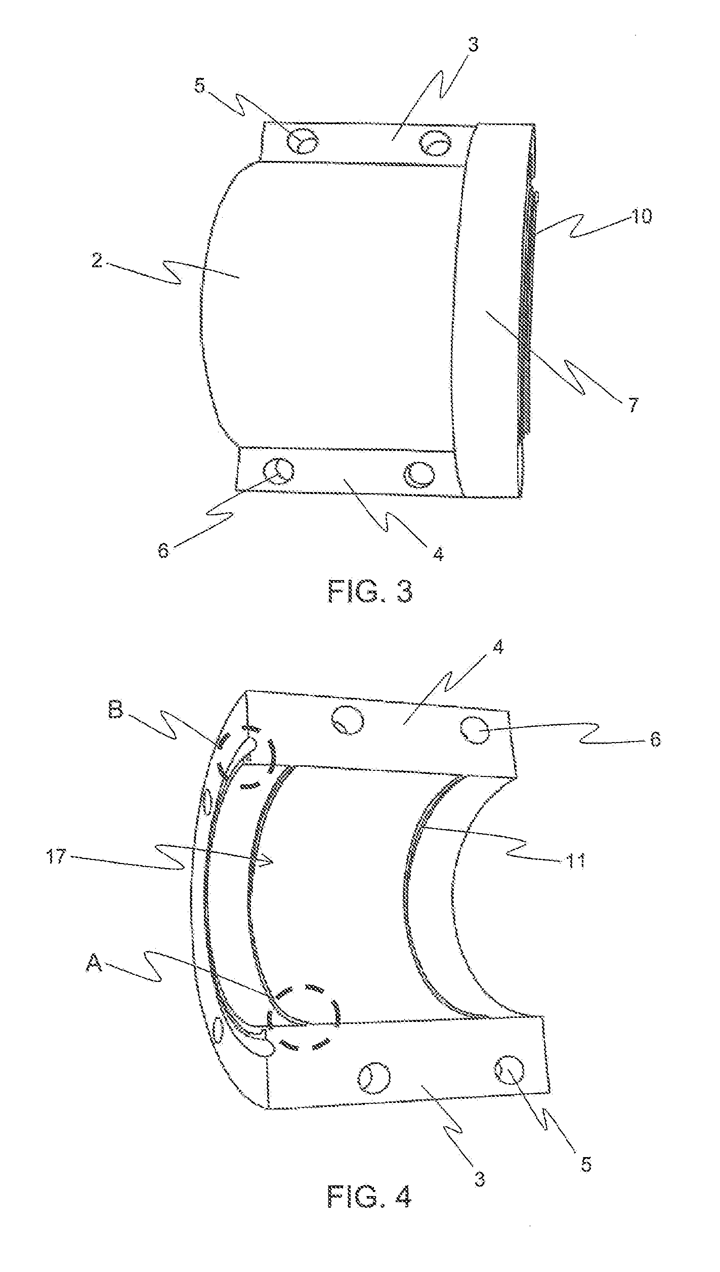
[0015]More specifically this invention refers to a coupling comprising four equal parts, and each one of them is shaped in the form of a semi-cylinder having the same outer dimensions as the pipe, as well as edges and holes that must be aligned for bolts, nuts and washers to be tightened. The internal part of the semi-circumference has at least two cross-section ribs in relief that sink as teeth into the pipe when tightened. The main face of the coupling parts facing each other to align the holes so as to connect the pipes is provided with flange having a projecting notch to receive the straight and smooth cut of each pipe to be joined and a groove where the rubber O-ring is placed. The four parts of the invention are made of polyamide plastic that expands as the moisture increases, thus achieving a better tightening against pipes and consequently a total sealing.

Problems solved by technology

In some couplings, both pipes ends to be joined must be inserted inside the coupling which resembles a tube (such as electrofusion couplings, Plasson, Gegorg Fischer, Straub Open Flex and Aqualok Superfit) while others require the presence of a rubber tube or packing in both pipes (e.g Victaulic, Straub Open Flex couplings) before installing the parts of the coupling, therefore it is not possible to observe the fit or separation between both pipes.
Singularities or separations in pipes contribute to the accumulation of product material, thus affecting the durability of the coupling as well as of the pipe in addition to the fact of causing loss of the solid element being conveyed.
These couplings have a very precise fit against pipes which makes difficult the installation of the couplings of the state of the art.
The documents above described disclose different types of couplings, however none of them allows quick joining or connection of the pipes.

Method used


Image

  • Coupling Element
  • Coupling Element
  • Coupling Element

Examples


Embodiment Construction

[0039]The present invention provides a joint which can be easily and quickly installed or uninstalled by means of simple and conventional tools that succeed in joining two pipes with a precise and perfect fit in both ends thereof, without requiring a specialized staff or special equipment to that end. HDPE pipes take the semi-circumference shape of the parts of the invention when parts are tightened against the pipes, thus achieving a precise and perfect fit between both ends to be joined. Thus, the coupling between the pipe ends to be joined is similar to only one piece inside, as no singularities or separations are present between the pipes. By using bolts, nuts, washers, the rubber O-ring and the polyamide plastic material of the coupling, total sealing is achieved between the pipes as well as to the outside of them.

[0040]A joint assembly for pipes ends is normally comprised by two couplings: a first coupling is located at one end of a first pipe and a second coupling is located ...


PUM

PropertyMeasurementUnit
Plasticityaaaaaaaaaa
Perimeteraaaaaaaaaa

Abstract

A coupling element (1) that allows forming an easy-to-install coupling with precise and perfect fit between pipes, consisting of a body and a cavity in said body for a pipe to be housed, wherein said semi-tubular body (2) has a first flange (3) in its first lower edge and a second flange (4) in its second lower edge; wherein a. first plurality of holes (5) is located in the first flange (3) and a second plurality of second holes (6) is located in the second flange (4); wherein the upper edge of the front face (16) of said body (2) has a semicircular flange (7) where a plurality of front holes (8) is located; where in said front face (16) of said body (2) includes a semicircular groove (9) concentrically located with respect to the semicircular cavity (17) of the coupling element (I) for an O-ring to be housed; where in the lower edge of said front face (16) includes a lower perimeter rim or projection (10) provided with a notch (12); and where in the lower face of the body (2), in said semicircular cavity (17) includes a plurality of ribs (11) designed to sink or indent into the outer surface of the pipe (14) so as to ensure sealing. The present invention also refers to the method of assembly of the coupling elements (1).

Description

TECHNICAL FIELD OF THE INVENTION[0001]This invention relates to a coupling formed by four equal parts each of them in the form of a semi-cylinder having the same external dimensions as the pipe, and edges with holes that must be aligned so as the bolts, nuts and washers can be tightened. The internal portion of the semi-cylinder has at least two cross-section ribs in relief to be sunk as teeth into the pipe at the moment this is being tightened. The main face of the parts of the coupling facing each other to align holes so as to connect the pipes has a flange with a projecting notch for a straight and smooth cut of each pipe to be joined and a groove to place the rubber O-ring. The four parts of the invention are made of polyamide plastic that expand as the moisture increases, thus achieving a better tightening against the pipes as well as a total sealing.BACKGROUND OF THE INVENTION[0002]Pipes joined by means of existing couplings are mainly used for conveying fluids and gases. Due ...

Claims


Application Information

Patent Timeline
IPC IPC(8): F16L23/00B23P11/00
CPCF16L23/024F16L23/032Y10T29/49826F16L47/20F16L47/14
Inventor VIDAL VIVALLO, VICTOR RAMONMARTINEZ ACEVEDO, SERGIO JAVIER
Owner VIMAR SOC COMERCIAL
Learn More