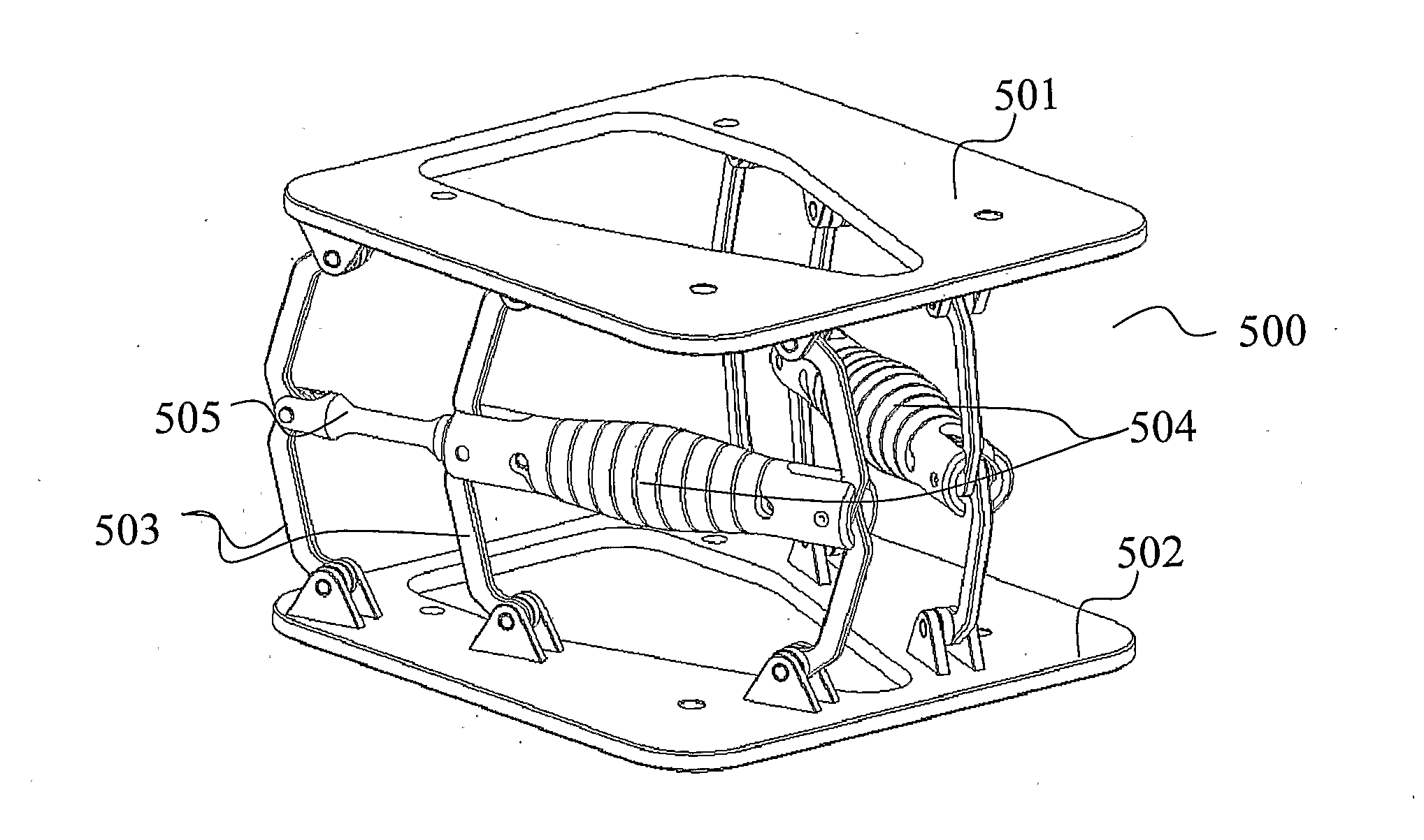
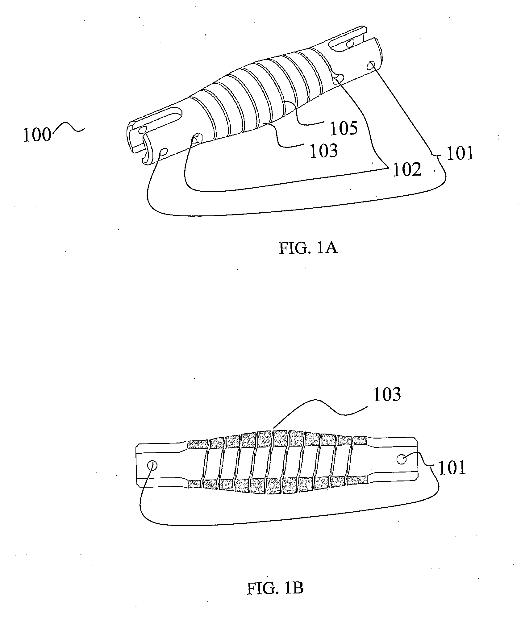
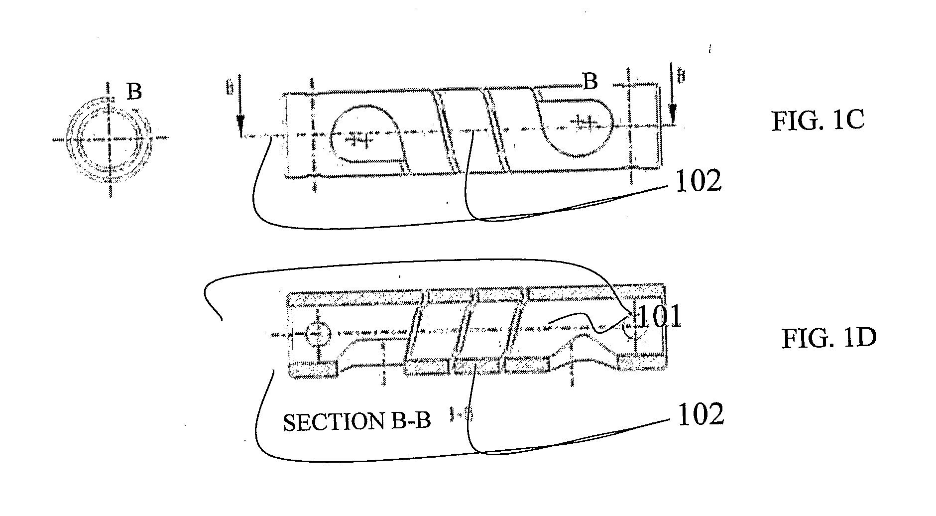
Shock absorbing mechanism with feet protection for vehicle and aircraft seats

a technology of shock absorption mechanism and vehicle seat, which is applied in the direction of vibration dampers, applications, movable seats, etc., can solve the problems of more complex design than needed, limited range of endurance of human body for acceleration, and disadvantage of described patents, etc., and achieves the effect of increasing stiffness

Active Publication Date: 2011-09-29
MOBIUS PROTECTION SYST
View PDF24 Cites 39 Cited by
  • Summary
  • Abstract
  • Description
  • Claims
  • Application Information

AI Technical Summary

Benefits of technology

[0071]It is an object of the present invention to provide the aforementioned method, further provided with strain relief provision

Problems solved by technology

In situations such as vehicle collisions and explosions due to mines and IEDs, a chief cause of injury is the extreme impulses experienced; the human body has limited range of endurance for accelerations over durations of time.
Furthermore the design relies on a conventional shock absorber and additional elements, which is a more complex design than needed for this application.
In applications where volume, height, and/or weight are limited the described patent will be at a disadvantage as compared to a device whose volume and weight does not increase to give increase travel.
In the described application of strain relief for electrical towers the volume and weight of the device are largely irrelevant, but it will be appreciated that in aircraft or vehicles the allowable weight and volume of such a device will be limited.
However it will be seen that the tunability of the stress-strain curve in this device is limited, when one considers that the ultimate stress the pad can provide is dependent upon the viscosity of the liquid within the spheres, which must take a value within a

Method used


Image

  • Shock absorbing mechanism with feet protection for vehicle and aircraft seats
  • Shock absorbing mechanism with feet protection for vehicle and aircraft seats
  • Shock absorbing mechanism with feet protection for vehicle and aircraft seats

Examples


Embodiment Construction

[0083]When an object undergoes impact, it experiences a large acceleration which for human beings can often be injurious or fatal. The acceleration experienced depends upon the difference between initial and final velocities and the distance over which the acceleration occurs,

a=Δv22dEquation1

[0084]Where Δv is the change in velocity, d is the distance over which the acceleration occurs, and a is the acceleration experienced. It will be seen that for a given Δv (which in many cases cannot be controlled, as in a crash where a car goes from cruising speed to zero) the acceleration experienced will be decreased by increasing d. Thus allowing the passenger of a vehicle as large a degree of travel within the vehicle body as possible may decrease the accelerations experienced to a less-injurious level. Similarly if the energy of the impacting object can be reduced, its velocity will be reduced and Δv will be decreased. In a seat intended to minimize injury from mines, the available travel d...


PUM

PropertyMeasurementUnit
Fractionaaaaaaaaaa
Fractionaaaaaaaaaa
Velocityaaaaaaaaaa

Abstract

The present invention discloses a method and apparatus for minimizing accelerations during impacts such as those encountered in motor vehicle accidents, helicopter and airplane crashes, explosions, and the like. The preferred embodiment takes the form of a helical spring-like member (100), designed to experience plastic deformation over a desired deformation length, under a given impact load threshold. The spring-like member is preferably installed in a mechanical linkage that is flattened under impact, straining the spring-like member in a predictable fashion. The operating characteristics of this system [namely the stress-strain curve, and thus the deformation length, impact load threshold, and acceptable load range for the system to be protected] can be easily controlled by varying the device dimensions and installation configuration.

Description

FIELD OF THE INVENTION[0001]The present invention relates to a method and apparatus for minimizing accelerations during impacts such as those encountered in motor vehicle accidents, airplane crashes, explosions, and the like.BACKGROUND OF THE INVENTION[0002]In situations such as vehicle collisions and explosions due to mines and IEDs, a chief cause of injury is the extreme impulses experienced; the human body has limited range of endurance for accelerations over durations of time. (See FIG. 9 for a chart of injury levels as function of acceleration in g (y-axis) vs. time (x-axis), [Eiband A. et al, 1959]). To lower the maximum impulse experienced, the distance through which the body travels when changing its initial to final velocity must be increased, or equivalently, the time during which the acceleration is experienced must be increased. For example, in a head-on collision of a vehicle with a rigid wall, the occupant's body will undergo a change from the car's initial speed to ze...

Claims


Application Information

Patent Timeline
IPC IPC(8): B60N2/427F16F7/12B23P13/00
CPCB60N2/24B60N2/4242B60N2/42709Y10T29/49615F16F7/128B64D11/0619B64D11/0689B60N2/16F16F1/06F16F7/12
Inventor MINDEL, SHYBAUM, MOSHE JACOBHASSAN, ANANENGEL, DAVID
Owner MOBIUS PROTECTION SYST
Why Eureka
Try Eureka