Methods for selecting and controlling devices

a technology for controlling devices and devices, applied in the direction of process and machine control, instrumentation, testing/monitoring control systems, etc., can solve the problems of voluminous remotes, complex remotes, and increased complexity of control panels, so as to reduce feedback signals, simplify wireless controllers, and shorten the delay of selecting and controlling

Active Publication Date: 2011-09-29
SIGNIFY HLDG BV
View PDF13 Cites 56 Cited by
  • Summary
  • Abstract
  • Description
  • Claims
  • Application Information

AI Technical Summary

Benefits of technology

[0004]Therefore, it would be advantageous to provide a method for selecting and controlling devices having a shorter selecting and controlling delay, based on wireless communication technology. It would also be advantageous to reduce feedback signals in the process of selecting and controlling to simplify the wireless controller, save energy and reduce electromagnetic radiation in the environment.
[0007]According to embodiments of the present invention, each device determines a different response time according to the different relative position with respect to the wireless controller, based on a predefined rule, i.e. the more a device's relative position matches that of the target device, the sooner this device will respond, and the sooner the wireless controller will receive its response, which significantly reduces the delay for selecting the target device; meanwhile, other devices do not respond when they find that there are devices matching the target device better than they do through detecting other's response signals, thus, their energy consumption as well as the transmission of the radio signals and the electromagnetic radiation in the area are reduced, and the processing complexity of the response signals in terms of the wireless controller will be simplified.

Problems solved by technology

As the number of devices increases, the control panel would become more complex with lots of buttons or knobs corresponding to the plurality of devices, and the user has to memorize which button controls the corresponding device.
Although wireless communication technology has been used to shorten the distance between the user and the control panel, for example a remoter to control each device remotely, the remoter is still complex because of lots of buttons, menus or options for each device.
So, the remoter is voluminous and its user interface is not very user-friendly.
As the number of devices increases, the amount of feedback signals also increases, thus the wireless controller needs more time to process and a higher processing capability; meanwhile, a large amount of feedback would increase the collision probability of the channel due to the random access method such as CSMA / CA, thus the wireless controller needs more time to collect all feedback signals from all devices.
These drawbacks result in a longer delay before selecting and controlling the target device via the wireless controller, and in an unsatisfactory user experience.

Method used


Image

  • Methods for selecting and controlling devices
  • Methods for selecting and controlling devices
  • Methods for selecting and controlling devices

Examples


embodiment 1

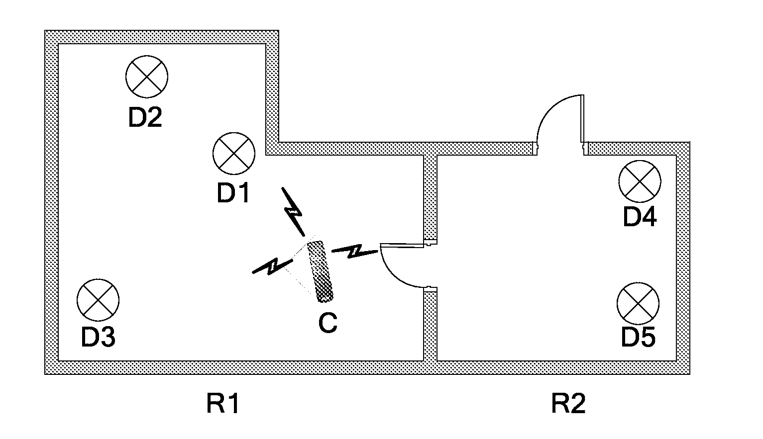
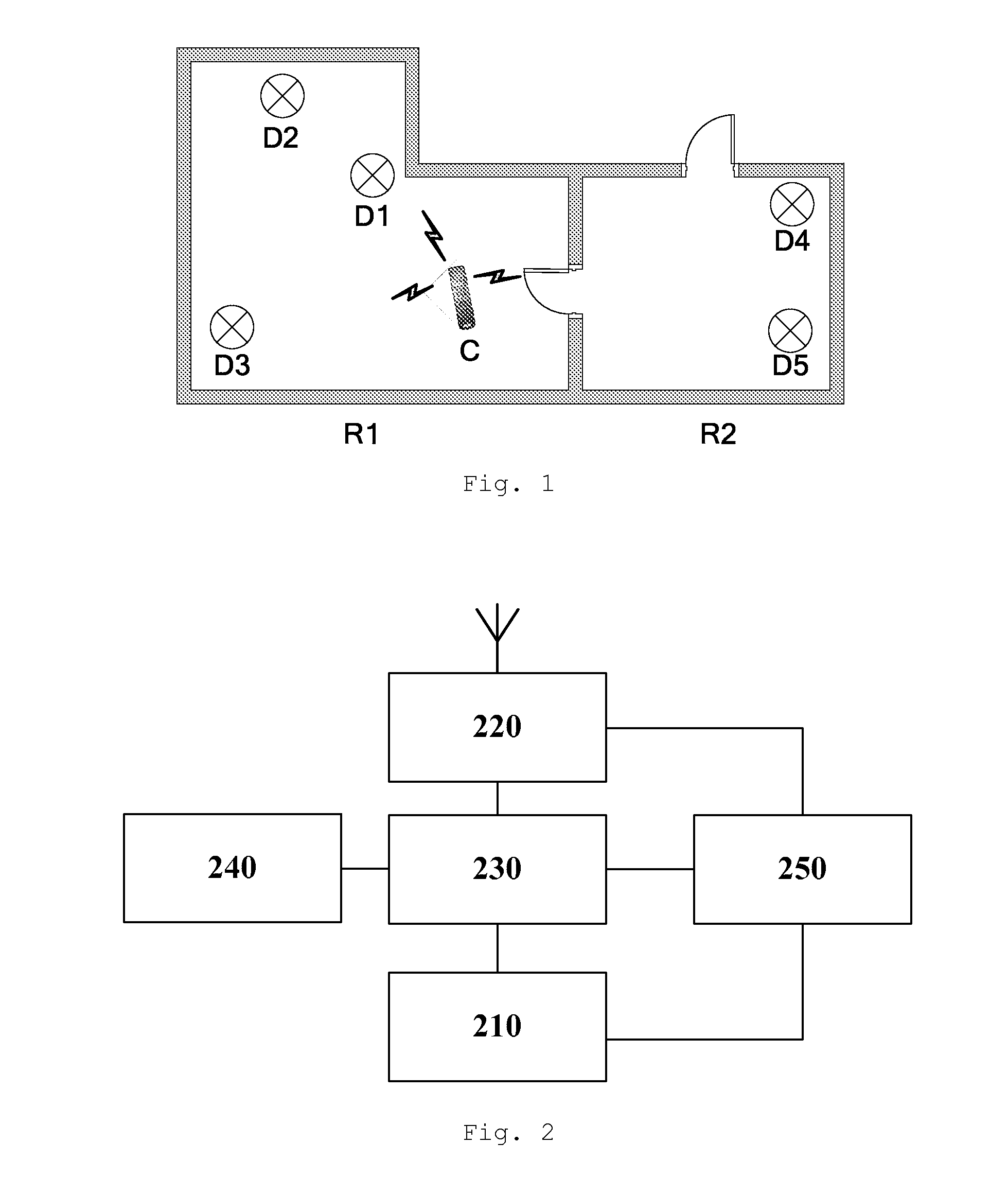
[0017]FIG. 1 shows a topology of a lighting area based on a wireless control network. This lighting area is an indoor environment and includes two neighboring rooms R1 and R2. Luminaires D1 through D3 are mounted in room R1, and D4 and D5 in room R2. A wireless controller C sends control signals to each luminaire by means of unicast or multicast, based on the unique identification of each luminaire, to control its lighting functions such as on / off, brightness, color, focus and rotation. The commissioning of the luminaires is completed, which means that the system knows the location of each luminaire. The method of commissioning is well-known to those skilled in the art, and the present invention will not give further details.

[0018]As shown in FIG. 2, each luminaire comprises a lighting component 210, a wireless communication module 220 using wireless protocols such as ZigBee™, a processor 230, a memory 240 and a power supply 250. The wireless communication module 220 communicates wi...

embodiment 2

[0061]As shown in FIG. 6, the transmitting antenna of the wireless controller C is directional, such as a directional antenna with beam-forming capacity. This kind of antenna has a relatively stronger transmitting power within the scope of angle A, such as the direction the wireless controller C is pointing to, and has a weaker transmitting power in another angle scope. Therefore, when the user wants to select the luminaire D2 and control it, he can direct his hand-held wireless controller C towards D2. In this way, the azimuth θ between the luminaire D2 and the transmitting angle of the wireless controller C (which is the angle between the direction of peak transmission and the direction to D2) is relatively small; while the azimuths of the luminaires D3 and D1 are relatively large.

[0062]Firstly, the wireless controller C broadcasts a probe message, and the transmitting power within the angle A is strong, while it is weak outside the angle A.

[0063]Subsequently, the luminaires havin...


PUM


Abstract

A method of selecting and controlling devices based on wireless communication technology. The wireless controller sends a probe message to one or more devices; each device receives the probe message, obtains information in respect of its relative position with respect to the wireless controller, determines a response time to respond according to a first predefined rule, based on its relative position information: detects response signals from other devices before expiration of the response time; decides whether to send or not to send its response signal according to a second predefined rule and the detecting procedure of response signals from other devices; the wireless controller receives response signals sent by the devices after the comparison of the relative position information of each device with respect to the wireless controller, and selects the target devices from the devices. Embodiments of the present invention reduce the complexity, delay and energy consumption of the selection for wireless devices, and are especially applicable for wireless lighting systems.

Description

FIELD OF THE INVENTION[0001]The present invention relates to the selection and control of devices, particularly to methods for selecting and controlling devices, based on wireless communication technology.BACKGROUND OF THE INVENTION[0002]In the indoor and outdoor environments where people live and work, various kinds of electronic and electrical devices are deployed, such as multiple luminaires located at different locations. A user selects and controls these devices to satisfy his working and living requirements. Currently, people usually use immobile controllers, such as a control panel mounted on the wall to control these devices. In this case, if a user wants to control a device, he must go to the control panel to manipulate the button or knob corresponding to the device. As the number of devices increases, the control panel would become more complex with lots of buttons or knobs corresponding to the plurality of devices, and the user has to memorize which button controls the co...

Claims


Application Information

Patent Timeline
Patent Type & Authority Applications(United States)
IPC IPC(8): G05B23/02
CPCG08C17/02G08C2201/71H05B37/0272H04W48/20G08C2201/91H05B47/19H05B47/155
Inventor FENG, LEIYANG, DAIQINCHEN, ZHIGANG
Owner SIGNIFY HLDG BV
Why Eureka
Try Eureka