Touch screen panel

Active Publication Date: 2011-09-29
SAMSUNG DISPLAY CO LTD
View PDF63 Cites 22 Cited by
  • Summary
  • Abstract
  • Description
  • Claims
  • Application Information

AI Technical Summary

Benefits of technology

[0023]According to exemplary embodiments of the present invention, each of the first and second connection patterns coupling the adjacent first or second sensing cells to each other is made of the same low resistance metal material as the metal pattern formed at the periphery of the touch screen panel, and each connection pattern is arranged not to overlap with each other to reduce the vulnerability of static electricity of the connection patterns, thereby making it possible to overcome an electrostatic discharge (ESD) probl

Problems solved by technology

However, an overlapping area of connection parts respectively located on the upper and lower layers becomes large, and

Method used


Image

  • Touch screen panel
  • Touch screen panel
  • Touch screen panel

Examples


first embodiment

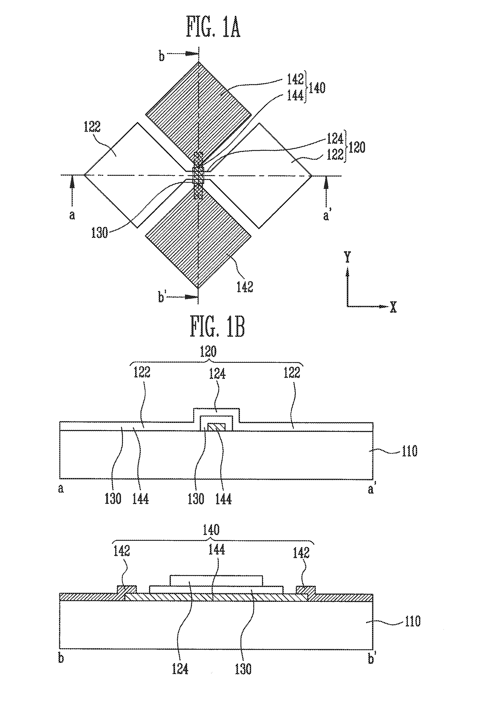
[0043]In the present invention, the second connection pattern 144 is below the first connection pattern 124, and an insulating layer 130 is formed between the first and second connection patterns 124 and 144 in order to prevent the short therebetween.

[0044]Here, the insulating layer 130 may be formed in the crossing region of the first and second connection patterns 124 and 144 as islands.

[0045]Further, the connection pattern 144 is made of low resistance metal. For example, the connection pattern 144 may be formed at an end of the display region in which the first and second sensing cells 122 and 142 are formed and may be made of the same material as a metal pattern for supplying the signals sensed by the sensing cells to a driving circuit side.

[0046]According to the structure of the embodiment of FIG. 1, the second connection pattern 144 is made of the low resistance metal material to minimize or reduce the width of the connection pattern, thereby making it possible to reduce the ...

second embodiment

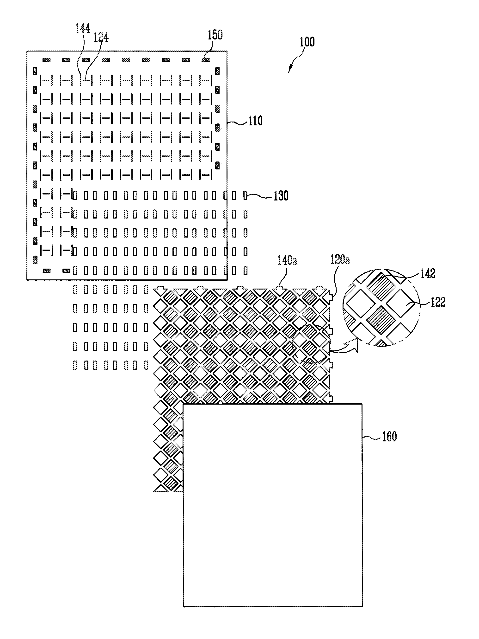
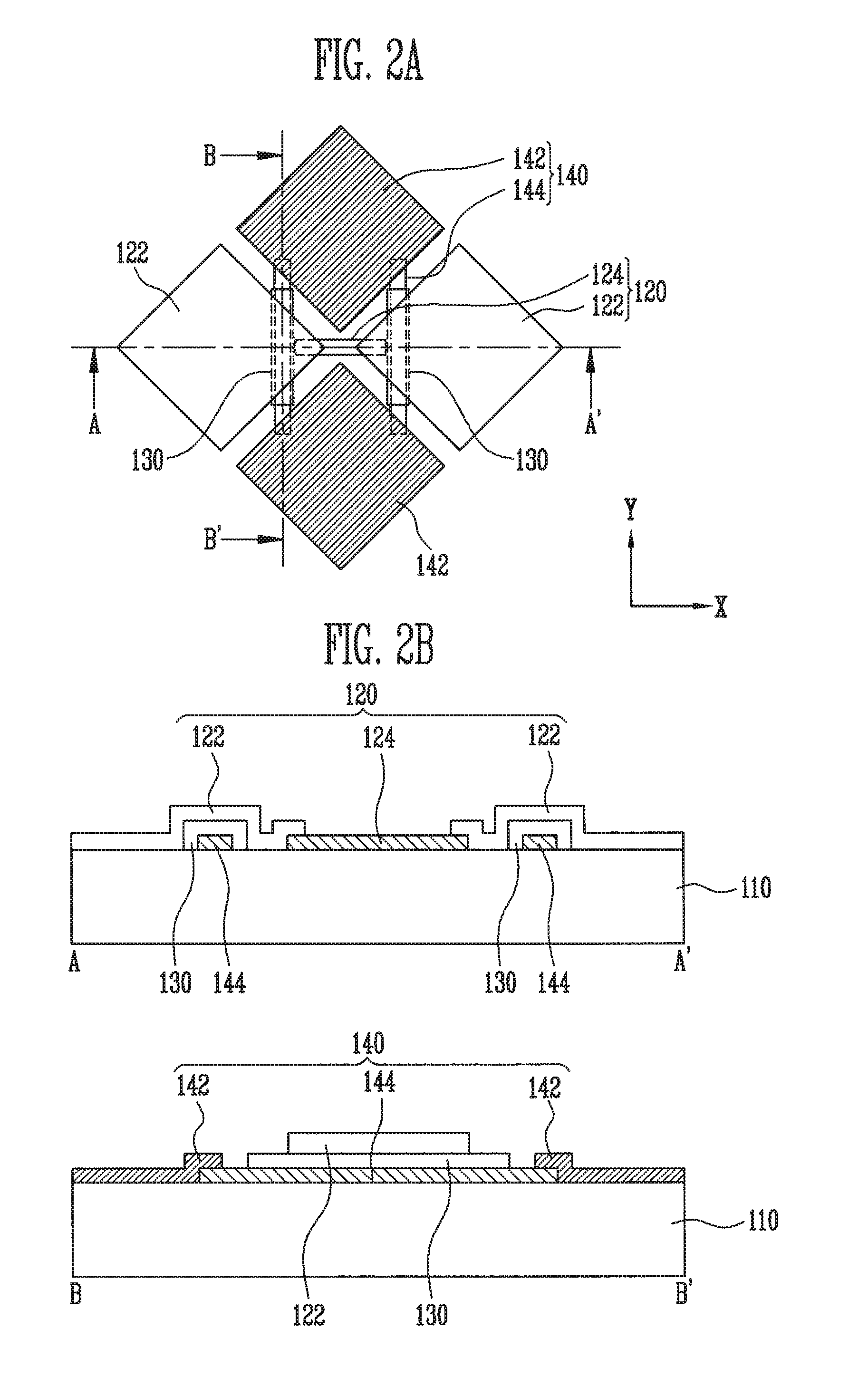
[0050]Referring to FIGS. 2A and 2B, sensing patterns according to the present invention include the first and second sensing patterns 120 and 140 that are alternately arranged. The second sensing patterns 140 are connected to each other in one column unit having the same X coordinate, and the first sensing patterns 120 are connected to each other in one row unit having the same Y coordinate.

[0051]Here, the first sensing patterns 120 are configured to include first sensing cells 122 arranged in one row having the same Y coordinate along a first direction (row direction) and a first connection pattern 124 that connects the adjacent first sensing cells 122 to each other, and the second sensing patterns 140 are configured to include second sensing cells 142 arranged in one column having the same X coordinate along a second direction (column direction) and a second connection pattern 144 that connects the adjacent second sensing cells 142 to each other.

[0052]Here, in the second embodimen...

third embodiment

[0073]More specifically, with the present invention, the first sensing cells 122 arranged in one row along the first direction whose Y coordinates are the same and the second sensing cells 142 arranged in one column along a second direction whose X coordinates are the same are formed on the transparent substrate 110.

[0074]Thereafter, the first connection pattern 124 contacting the ends of the first sensing cells 122 is formed so that the adjacent first sensing cells 122 are electrically connected to each other, and the second connection pattern 144 contacting the ends of the second sensing cells 142 is formed so that the adjacent second sensing cells 142 are electrically connected to each other.

[0075]However, even in this case, the second connection pattern 144 overlaps with a portion of the first sensing cell 122, and the insulating layer 130 is formed between the overlapping second connection pattern 144 and first sensing cell 122 in order to prevent the second connection pattern ...


PUM


Abstract

A touch screen panel includes: a flat panel display including an upper substrate, a lower substrate, and pixels arranged on a display region of the lower substrate in a stripe arrangement; first sensing cells arranged in a first direction on the upper substrate and second sensing cells arranged in a second direction on the upper substrate; first connection patterns electrically connecting adjacent ones of the first sensing cells to each other in the first direction, and second connection patterns electrically connecting adjacent ones of the second sensing cells to each other in the second direction, wherein at least one of the first connection patterns and the second connection patterns is inclined so that it partially overlaps with the pixels.

Description

[0001]This application claims priority to and the benefit of Korean Patent Application No. 10-2010-0025660, filed on Mar. 23, 2010, in the Korean Intellectual Property Office, the entire content of which is incorporated herein by reference.BACKGROUND[0002]1. Field[0003]Aspects of embodiments according to the present invention relate to a touch screen panel.[0004]2. Description of Related Art[0005]A touch screen panel is an input device that allows a user to use a hand or an object to select contents displayed on a screen such as an image display device, etc.[0006]To this end, the touch screen panel is provided on a front face of the image display device and generates electrical signals corresponding to positions directly contacted by a person's hand or an object. Therefore, the command contents selected at the contact position are received as the input signals. As the touch screen panel can replace a separate input device that is operated by being connected with the image display de...

Claims


Application Information

Patent Timeline
IPC IPC(8): G06F3/041
CPCG06F3/044G06F2203/04111G06F2203/04103G06F3/0443G06F3/0446G06F3/0412
Inventor KIM, DO-YOUBKWAK, WON-KYUJANG, BRENT
Owner SAMSUNG DISPLAY CO LTD
Why Eureka
Try Eureka