Display device and driving method thereof

a technology of display device and driving method, which is applied in the direction of color television details, television systems, instruments, etc., can solve the problems of hardly increasing black insertion rate and contributing to image quality enhancement, and achieve the effect of increasing the gray level range and black insertion ra

Active Publication Date: 2011-09-29
JOLED INC
View PDF9 Cites 16 Cited by
  • Summary
  • Abstract
  • Description
  • Claims
  • Application Information

AI Technical Summary

Benefits of technology

[0015]According to the display device and the driving method thereof according to an implementation of the present invention, the black insertion rate can be increased relative to a portion which has a low luminance level, by finely setting the black insertion rate on a line-by-line basis. Accordingly, it is possible to resolve the moving image blur, and also to increase range of gray levels in a portion with dark gray levels.

Problems solved by technology

However, the black insertion rate is hardly increased relative to the portion having a low luminance level, which does not greatly contribute to enhancing the image quality such as increasing the gray level.

Method used


Image

  • Display device and driving method thereof
  • Display device and driving method thereof
  • Display device and driving method thereof

Examples


embodiment 1

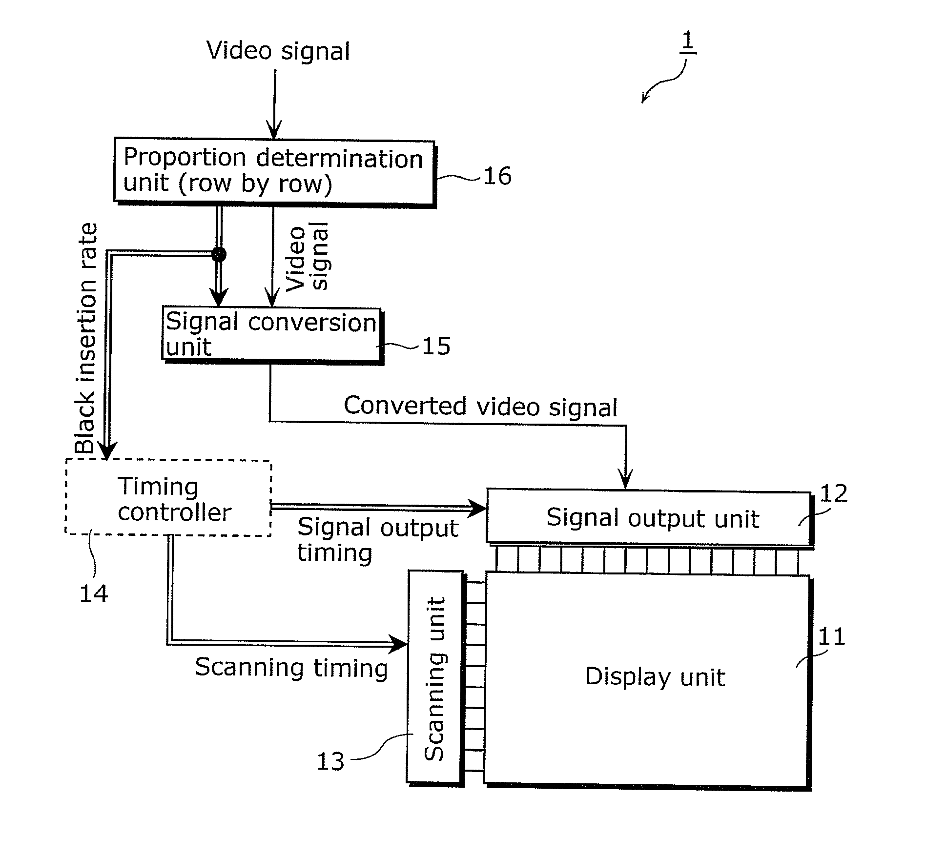
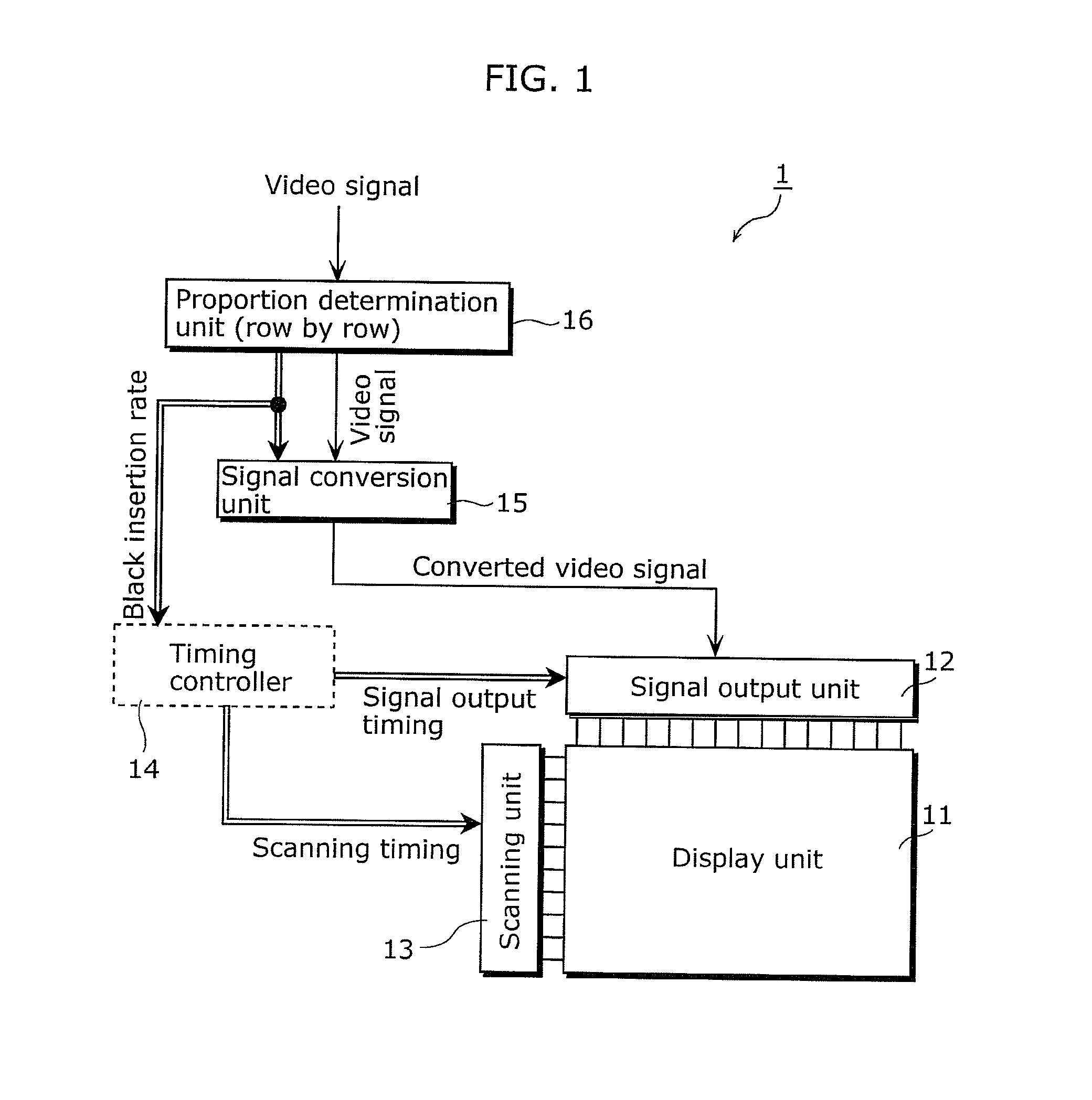
[0051]FIG. 1 is a functional block diagram of a display device according to Embodiment 1 of the present invention. A display device 1 shown in FIG. 1 includes a display unit 11, a signal output unit 12, a scanning unit 13, a timing controller 14, a signal conversion unit 15, and a proportion determination unit 16.

[0052]Hereinafter, references are made to functions and structures of the respective units.

[0053]The display unit 11 includes a plurality of light-emitting pixels arranged in a matrix. Each light-emitting pixel includes a display element. Here, the display element is an element which emits light by an electric signal corresponding to a video signal externally input. Examples of the display element include an organic electroluminescent (hereinafter, referred to as EL) element or a liquid crystal element.

[0054]The proportion determination unit 16 has a function to determine the proportion of a non-video signal period, during which the display element is caused not to emit lig...

embodiment 2

[0091]The present embodiment is different from Embodiment 1 in the method for supplying a non-video signal which does not cause emission of light that is based on a video signal input to a light-emitting element.

[0092]FIG. 6 shows a fundamental circuit configuration diagram of light-emitting pixels included in the display unit according to Embodiment 2 of the present invention. The display unit 21 shown in FIG. 6 includes light-emitting pixels arranged in a matrix. The respective light-emitting pixels include a driving transistor 111, a selecting transistor 112, an organic EL element 113, a data line 114, a gate line 115, a positive power supply line 116, a negative power supply line 117, a capacitor 218, and a control line 219.

[0093]The display unit 21 shown in FIG. 6 is different from the display unit 11 shown in FIG. 4 in that a capacitor having a function to apply a bias voltage and a control line 219 are added. Hereinafter, differences are described while descriptions of the po...


PUM


Abstract

A display device includes a display that includes display elements arranged in lines of a matrix. Each display element is configured to emit light based on a video signal that is received by the display. A proportion determiner is configured to determine, for each line, a proportion of a single frame period during which each display element of a corresponding line is not to emit the light. A signal converter is configured to convert an amplitude of the video signal for each line according to the proportion determined for each line. A signal output is configured to output the video signal converted by the signal converter to the display as a converted video signal. A scanner is configured to output a scanning signal to the display for each line for inputting the converted video signal to the display elements of each line based on the proportion determined for each line.

Description

CROSS REFERENCE TO RELATED APPLICATION[0001]This is a continuation application of PCT Application No. PCT / JP2010 / 000440 filed on Jan. 26, 2010, designating the United States of America, the disclosure of which, including the specification, drawings and claims, is incorporated herein by reference in its entirety.BACKGROUND OF THE INVENTION[0002]1. Field of the Invention[0003]The present invention relates to a display device and a driving method thereof, and in particular, to a hold-type display device and a driving method thereof.[0004]2. Description of the Related Art[0005]In a hold-type display device such as a liquid crystal display or an organic electro-luminescent (EL) display, unlike an impulse-type display device such as a cathode ray tube (CRT) display, an image is continuously held during a frame period, which makes a moving image unclear. More specifically, in the case of the hold-type display device, an image is held and displayed as a still image in a frame period, and th...

Claims


Application Information

Patent Timeline
Patent Type & Authority Applications(United States)
IPC IPC(8): H04N5/57
CPCG09G3/2014G09G3/3233G09G2300/0842G09G2300/0876G09G2310/063G09G2320/0271G09G2320/066G09G2360/16G09G2320/0261
Inventor NAKAMURA, MIKA
Owner JOLED INC
Why Eureka
Try Eureka