
Blade outer seal for a gas turbine engine

a gas turbine engine and outer seal technology, which is applied in the direction of liquid fuel engines, machines/engines, mechanical equipment, etc., can solve the problems of affecting the ability of the aforesaid cooling aperture to adequately cool the outer seal (boas), being subject to high temperatures, and being relatively inefficient in others

Inactive Publication Date: 2011-09-29
RAYTHEON TECH CORP
View PDF25 Cites 28 Cited by
  • Summary
  • Abstract
  • Description
  • Claims
  • Application Information

AI Technical Summary

Benefits of technology

"The invention provides a blade outer air seal for a gas turbine engine, which includes a body with cooling air apertures that direct cooling air parallel to the inner radial surface of the engine. This design helps to improve engine performance and efficiency by reducing air leakage and improving air flow. The gas turbine engine that includes this blade outer air seal also has improved performance and efficiency."

Problems solved by technology

During operation of the engine, the blade outer air seal (BOAS) is typically subject to high temperatures induced by extremely high core gas temperatures.
This type of cooling is useful in some applications, but is relatively inefficient in others.
If the blade tips engage (i.e., “rub”) the BOAS, however, the result of this engagement can compromise the ability of the aforesaid cooling apertures to adequately cool the BOAS.

Method used


Image

  • Blade outer seal for a gas turbine engine
  • Blade outer seal for a gas turbine engine
  • Blade outer seal for a gas turbine engine

Examples


Embodiment Construction

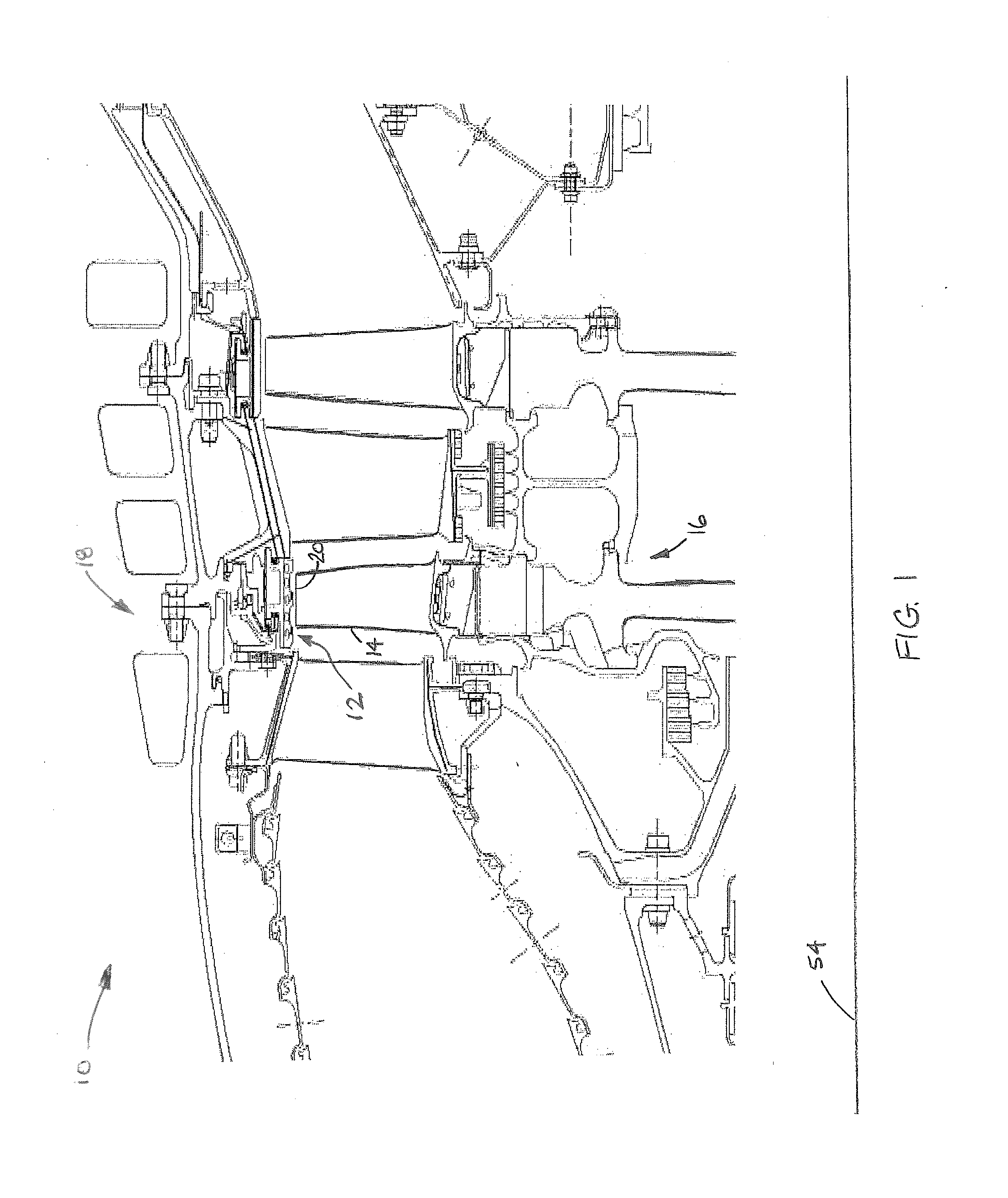
[0012]Referring to FIG. 1, a section of a gas turbine engine 10 includes a blade outer air seal 12 (hereinafter “BOAS”) disposed between a plurality of circumferentially disposed rotor blades 14 of a rotor stage 16 and an annular outer engine case 18 (hereinafter “engine case”). In the present embodiment, the BOAS 12 includes a plurality of circumferentially extending segments and is adapted to limit air leakage between blade tips 20 and the engine case 18.

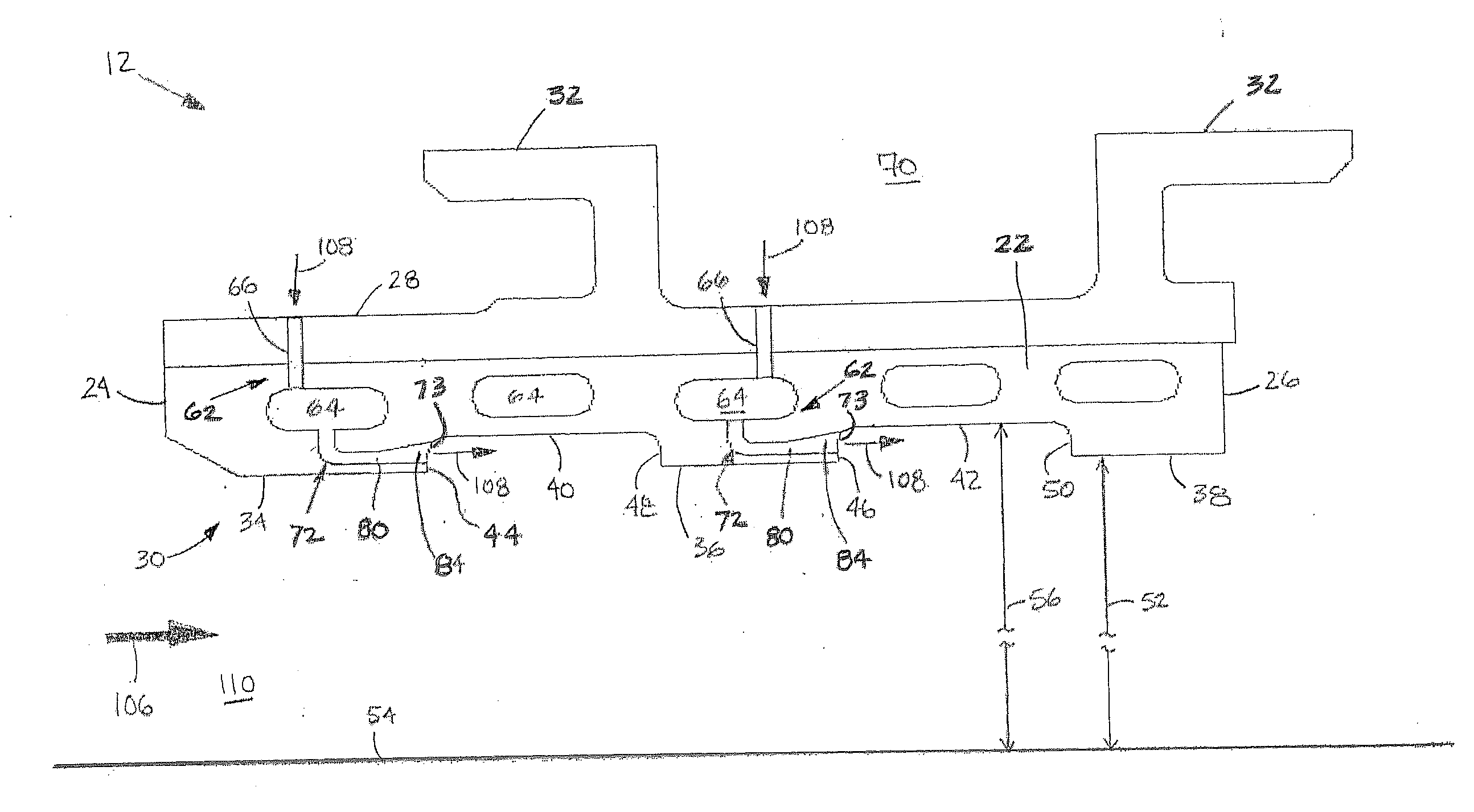
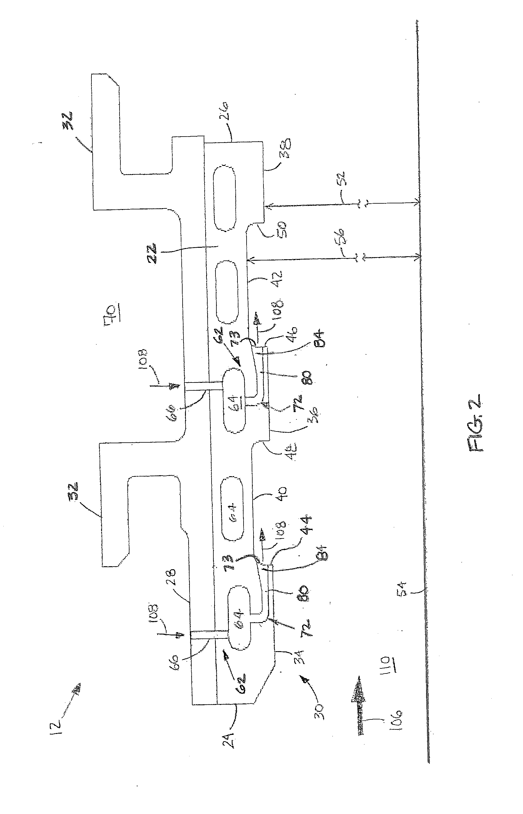
[0013]Referring to FIGS. 2 and 3, each segment of the BOAS 12 includes a body 22 that axially extends between a forward edge 24 and an aft edge 26, and radially extends between an outer radial surface 28 and an inner radial surface 30. When assembled, the BOAS inner radial surface 30 is disposed adjacent the rotor blade tips 20. One or more mounting features 32 (e.g., hooks, flanges, etc.) extend radially out from the outer radial surface 28 of each BOAS 12 for engagement with hardware connected to the engine case 18 (see FIG. 1)....


PUM


Abstract

A blade outer air seal for a gas turbine engine is provided. The blade outer air seal includes a body having an outer radial surface, an inner radial surface, and a plurality of cooling air apertures. The body extends between a forward edge and an aft edge. The inner radial surface includes at least one first seal section, at least one second seal section, and a riser extending radially between the first seal section and the second seal section. Each of the plurality of cooling air apertures extends between the outer radial surface and the riser, and each cooling air aperture has an exit configured to direct cooling air substantially parallel to the second seal section of the inner radial surface.

Description

BACKGROUND OF THE INVENTION[0001]1. Technical Field[0002]This disclosure relates generally to a blade outer air seal for a gas turbine engine and, more particularly, to a cooled blade outer air seal.[0003]2. Background Information[0004]A typical section of a gas turbine engine includes a blade outer air seal (or shroud) disposed between the blades of a rotor stage and an engine case. During operation of the engine, the blade outer air seal (BOAS) is typically subject to high temperatures induced by extremely high core gas temperatures. To maintain part integrity, BOAS are often cooled with air bled from a compressor section of the engine. In some instances, the BOAS are internally cooled by directing cooling air through a plurality of internal passages, and exiting that cooling air in a manner such that it is injected substantially radially into the core gas path. This type of cooling is useful in some applications, but is relatively inefficient in others. In other instances, the co...

Claims


Application Information

Patent Timeline
Patent Type & Authority Applications(United States)
IPC IPC(8): F02C7/28F01D11/10
CPCF01D5/20F05D2240/11F01D11/10
Inventor KNAPP, JAMES N.LUTJEN, PAUL M.THOLEN, SUSAN M.
Owner RAYTHEON TECH CORP
Learn More