[0010]Even when properly treated,
wound healing requires that the tissue comprising the wound
bed receives nutrients and other healing promoting factors. Generally, such factors are delivered to the wound
bed through the
circulatory system. The
blood supply to wounded tissue, unfortunately, is often diminished or compromised. Consequently, the amount of healing promoting factors reaching wounded tissue is often reduced.
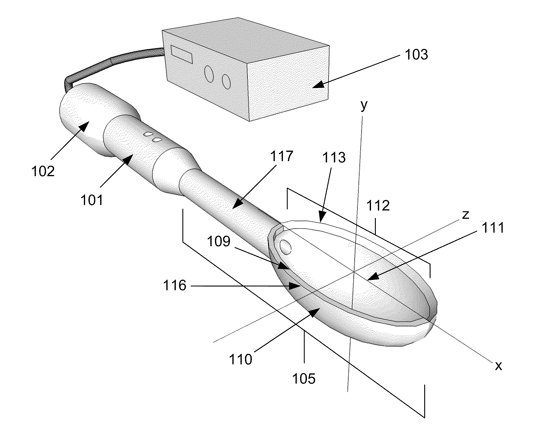
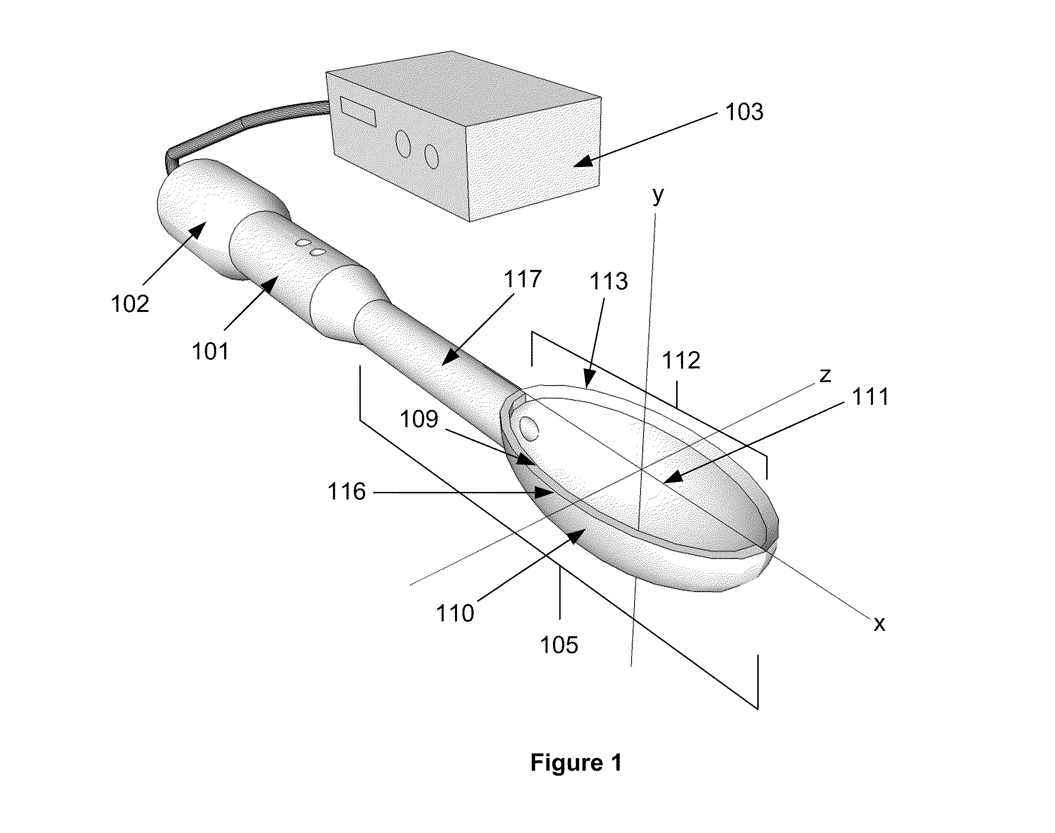
[0012]When driven or otherwise activated by the generator, the ultrasonic
transducer induces ultrasonic vibrations within the tip causing ultrasonic energy to be released from the various surfaces of the tip. Directly contacting a wound and / or tissue with the vibrating tip causes the ultrasonic energy emanating from the various surfaces of the tip to enter the wound and / or tissue. The ultrasonic energy entering the wound and / or tissue reduces sensitivity to pain. Releasing ultrasonic energy into a wound and / or tissue is suspected, but not known, to change the permeability of cellular membranes to ions and / or other molecules within the
extracellular environment, which may include components of the therapeutic solution. Changing
membrane permeability may disrupt ionic and / or other chemical gradients relied upon by the cells to respond to painful stimuli and increase the availability of
active components of the therapeutic solution.
[0013]When the
transducer is activated, ultrasonic energy is also released from the walls of the
paraboloid cavity. Configuring the walls of the cavity to form a parabola in at least two dimensions as to form a
paraboloid may focus the ultrasonic energy emanating from the walls of the cavity towards the foci of the parabolas. If the foci of the parabolas lie outside the cavity, then the ultrasonic energy emitted from the cavity may be concentrated towards a point below the surface of the wound and / or tissue to be treated. Concentrating the ultrasonic energy emitted from the cavity at a point below the surface of the wound and / or tissue may elicited a greater change in the
membrane permeability of deep cellular structures such as, but not limited to, axons and somas, further decreasing the
sensation of pain in the wound and / or tissue to be treated.
[0014]As to facilitate the transmission of ultrasonic energy from the walls of the cavity to a wound and / or tissue to be treated, the therapeutic solution may fill the cavity and act as a
coupling medium by conducting vibrations from the walls of the cavity to the wound and / or tissue to be treated. When the tip is ultrasonically vibrated, cavitations may form within the therapeutic solution. Additionally or in the alternative, the therapeutic solution may be atomized in the cavity into a spray. If a piezoelectric transducer is used to induce the horn and tip to vibrate approximately in
resonance, then the
voltage of the electrical
signal driving the transducer will largely control the degree to which the therapeutic solution is cavitated and / or atomized. At low voltages, the solution within the cavity will be cavitated to a small degree. As the
voltage increases, the amount of cavitations within the solution is increased. Further increasing the
voltage will eventually induce atomization of the solution. Regardless of whether the solution is atomized and / or cavitated within the cavity, the presence of the solution within the cavity may couple the transmission of ultrasonic energy released from the walls of the cavity to the wound and / or tissue to be treated.
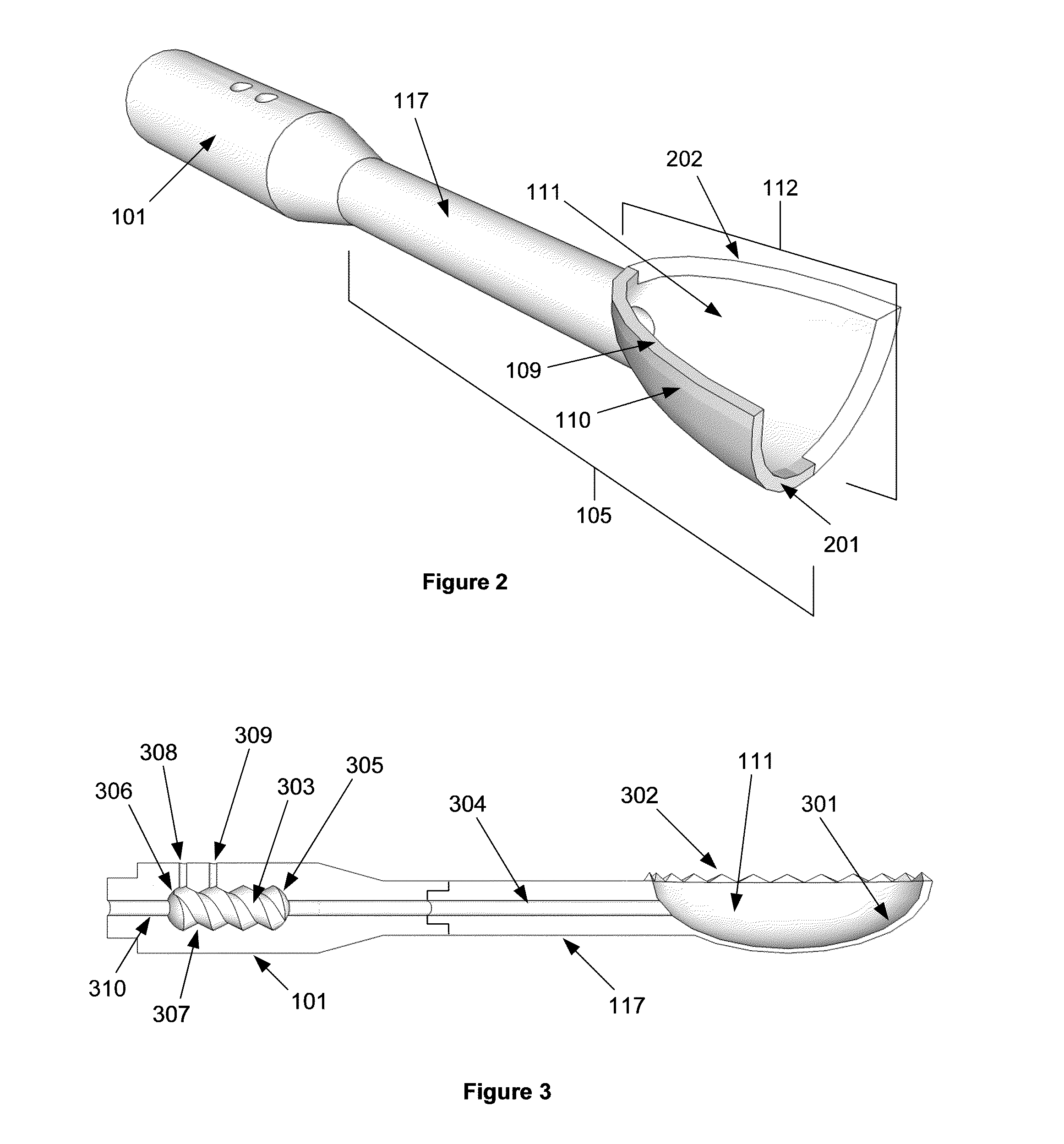
[0016]As the vibrations travel back-and-forth within the chamber, they may strike protrusions located on the side walls of the chamber. After striking a protrusion, the vibrations are scattered about the chamber. Consequently, some the vibrations echoing off the side wall protrusions may be reflected back towards the wall of the chamber from which they originated. Some the vibrations may continue on towards the opposite the wall of the chamber. The remainder of the vibrations may travel towards another side wall of the chamber where they will be scattered once more by the protrusion. Therefore, the echoing action of ultrasonic vibrations within the chamber is enhanced by the protrusions on the side walls of the chamber. Emitting ultrasonic vibrations into the chamber from their distal facing edges, the protrusions within the inner chamber may also enhance the mixing of the healing factor and carrying agent by increasing the amount of ultrasonic vibrations within the chamber.
[0023]Various degrees of debridement may be achieved by scrapping various portions of the tip across the wound and / or tissue. For example, scrapping
cutting members secured to the tip across the wound and / or tissue aggressively debrides diseased, necrotic, and / or other unwanted tissue.
Cutting members may be located at the opening of the cavity and / or on the various surfaces of the tip. Ultrasonic energy released from the
cutting members and / or the vibrations of the cutting members may fragment and / or emulsify the tissue being debrided, which may reduce the amount of force needed to be applied to cutting members to perform debridement. Furthermore, the ultrasonic energy released from and / or the vibrations of the cutting members permits aggressive debridement with a dull cutting edge. A moderate degree of debridement may be achieved by scrapping blunt edges within the tip across wound and / or tissue to be treated. Scrapping smooth surfaces of the tip across the wound and / or tissue to be treated may produce a mild debridement.


