
Cutting device and method

A technology of cutting machine and telescopic mechanism, applied in welding/cutting auxiliary equipment, shearing device, auxiliary device, etc., can solve the problems of difficult operation, twisting together, and difficult positioning of cutting position, and achieve the effect of improving construction efficiency

Inactive Publication Date: 2009-07-29
NINGBO CONSTR ENG GROUP
View PDF1 Cites 32 Cited by
  • Summary
  • Abstract
  • Description
  • Claims
  • Application Information

AI Technical Summary

Problems solved by technology

This patented cutting device requires a crane to hoist the cutting machine into the pipe, so it can only be used for vertically placed pipes from top to bottom, and the positioning of the cutting position is not easy to be precise; in addition, the arc can only be started in the pipe, and the The plasma arc cutting effect cannot be seen, and it is not easy to operate; the compressed air pipes, cables, etc. are dragged behind, and will be twisted together after cutting and turning

Method used


Image

  • Cutting device and method
  • Cutting device and method

Examples


Embodiment Construction

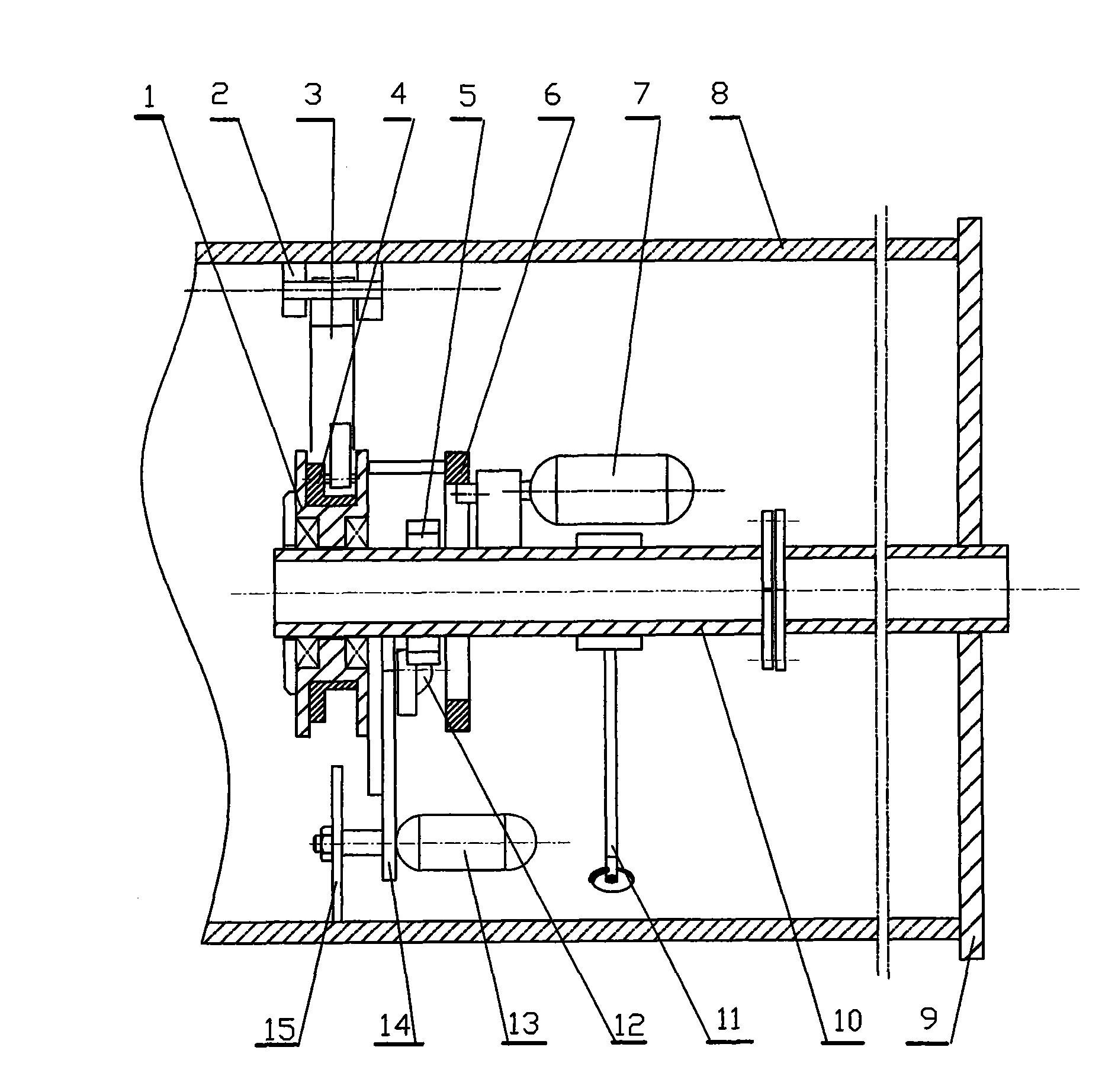
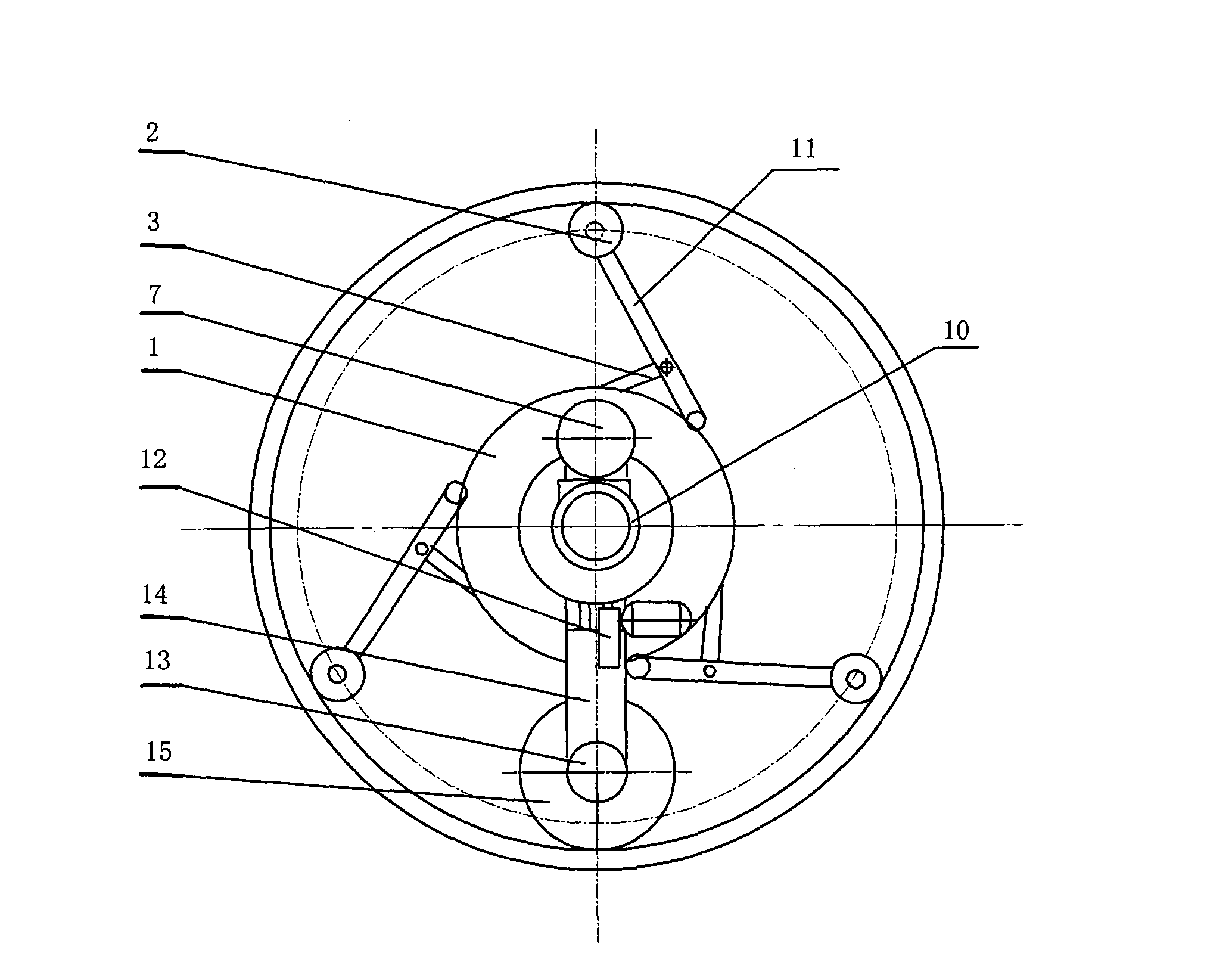
[0016] to combine figure 1 , figure 2 , the embodiment is to describe the cutting method of the cutting machine. Cutting machine is put into from cut pipe 8, is put into the position that needs cutting, and stretches into depth and is regulated by center pipe 10 and fixed plate 9. Start the positioning wheel expansion mechanism 3, the positioning wheel assembly 2 on the cutting machine is pushed out, and touches the inner wall of the steel pipe pile, so that the cutting machine is positioned in the middle of the cut pipe 8; the control motor 12 drives the telescopic mechanism 14 to push the cutting head outward , the grinding wheel sheet 15 tends towards the inner wall of the steel pipe pile, and simultaneously starts the motor on the cutting head 13 (this motor is connected with the cutting head, and the serial number is not marked), so that the grinding wheel sheet rotates at a high speed, and implements cutting from the inner wall to the outer diameter direction; start si...


PUM


Abstract

The invention relates to a cutting machine and a cutting method for mechanical equipment, and is designed aiming at the fact that cleaning of a long section of a pile foundation of the prior building engineering is realized by implementing cutting from the periphery of a steel pipe pile, so that the construction efficiency is reduced. The design key points of the invention comprise that: the cutting machine is arranged inside the steel pipe pile, and the extending depth is adjusted through a central pipe and a fixed plate; the central pipe is fixedly connected with a plane of the steel pipe pile; a rotary platform component which is connected with the radial surface is connected with a rotary disc, a positioning wheel extending mechanism and a positioning wheel component; an output shaft of a rotary motor is connected with a gear component, an electrically conductive sliding block component and the rotary disc; a control motor is connected with a telescopic planker; a cutting motor is connected with the telescopic planker and a grinding wheel; the radial surface of the central pipe is connected with the positioning wheel extending mechanism and an auxiliary wheel carrier which provides a driving force for the grinding wheel; and the high speed rotational grinding wheel forms a circle of cutting line along the inner wall of the steel pipe pile so as to complete cutting of the steel pipe pile which is a section higher from the inside diameter to the outside diameter. The cutting machine and the cutting method solve the technical problems of cutting of the steel pipe pile and are particularly suitable for project cleaning of a complete stage of the pile foundation.

Description

technical field [0001] The invention relates to the field of mechanical processing technology and equipment, and relates to equipment and a method for cutting a pipe from inside to outside. Background technique [0002] In processing practice, in some cases, it is necessary to cut the pipe from the inside to the outside with a pipe diameter below 600 mm and inconvenient for people to enter. For example, a section of the pipe that has been buried in the pipe trench must be cut off. In addition, steel pipe piles in construction projects also need such a cutting process: due to the complexity of geological conditions in construction projects, there is often a certain error between the driving depth of steel pipe piles and the design, so that steel pipe piles for building foundations are usually It is a bit higher than the design height. For buildings with basements, the elevation of these steel pipe piles is several meters underground. When it is necessary to cut the steel pi...

Claims


Application Information

Patent Timeline
Patent Type & Authority Applications(China)
IPC IPC(8): B23D21/14B23D33/00B23K7/00B23K7/10B23K10/00B23K37/02B23K101/06
Inventor 李水明陈黎明巫秀萍刘用海翁史俊肖秀丽
Owner NINGBO CONSTR ENG GROUP
Learn More