Magnetic screw

a magnetic screw and screw body technology, applied in the field of magnetic screws, can solve the problems of large increase in manufacturing costs, lack of mass productivity, and difficulty in spiraling continuously without a number of permanent magnets, and achieve the effects of increasing the axial thrust force, high efficiency of magnetic coupling, and simple construction

Inactive Publication Date: 2000-08-29
KOYO MASCH IND CO LTD +1
View PDF8 Cites 31 Cited by
  • Summary
  • Abstract
  • Description
  • Claims
  • Application Information

AI Technical Summary

Benefits of technology

A first object of the invention is to provide a magnetic screw which has a high efficiency of magnetic coupling between the magnetic nut and the screw shaft to increase the axial thrust force in the screw shaft and which is simple in construction and superior in mass productivity.

Problems solved by technology

Since the former magnetic screw requires a number of permanent magnets to be spirally arranged internally of the housing of the magnetic nut, there are disadvantages that it is structurally very complicated, that the operation of mounting these permanent magnets on the inner periphery of the housing is very troublesome, and that the magnetic screw lacks in mass productivity, leading to a large increase in manufacturing costs.
Furthermore, there are other disadvantages that it is difficult to arrange a number of permanent magnets spirally continuously without a gap and that the axial thrust force in the screw shaft cannot be increased.
Therefore, there is a disadvantage that the magnetic coupling between the magnetic nut 32 and the screw shaft 30 is so low that even if the magnetizing force of the individual N- and S-poles of the magnet bodies 35 are increased, the axial thrust force in the screw shaft 30 cannot be increased.
Further, as shown in FIG. 9, since the inner peripheral surfaces of the magnet bodies 35 are magnetized to spirally provide alternating N- and S-poles, there is a disadvantage that when the screw pitch is small, the magnetization itself of the inner peripheral surfaces of the magnet bodies 35 is very difficult or impossible to perform, which means that a magnetic screw having a small pitch cannot be produced.

Method used


Image

  • Magnetic screw
  • Magnetic screw
  • Magnetic screw

Examples


first embodiment

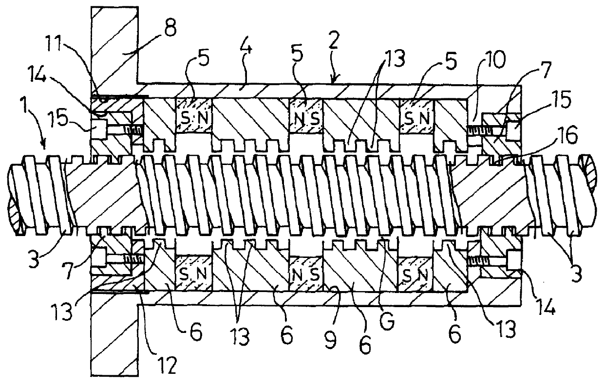
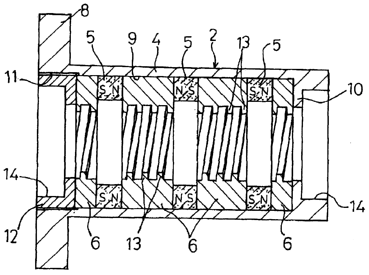
FIGS. 1 through 3 shows a magnetic screw according to the invention.

This magnetic screw, as shown in FIGS. 1 and 2, comprises a screw shaft 1 of magnetic material, and a magnetic nut 2 fitted on the outer periphery of the screw shaft 1. The screw shaft 1 is formed on its outer peripheral surface with thread crests 3 with a fixed pitch and a predetermined lead. In addition, a square thread whose crests 3 have a square cross section is used for the screw shaft 1.

The magnetic nut 2 has a housing 4 of non-magnetic material, such as stainless steel, and annular magnets 5 and annular yokes 6 are alternately fitted in said housing 4, with two guide rings 7 disposed at the axial ends.

In addition, the magnetic nut 2 is fixed to the table of a feed device or the like and is movable axially of the screw shaft 1.

The housing 4 is a long, substantially cylindrical body extending axially of the screw shaft 1. The housing 4 is integrally formed with an attaching flange 8 on the outer periphery ther...
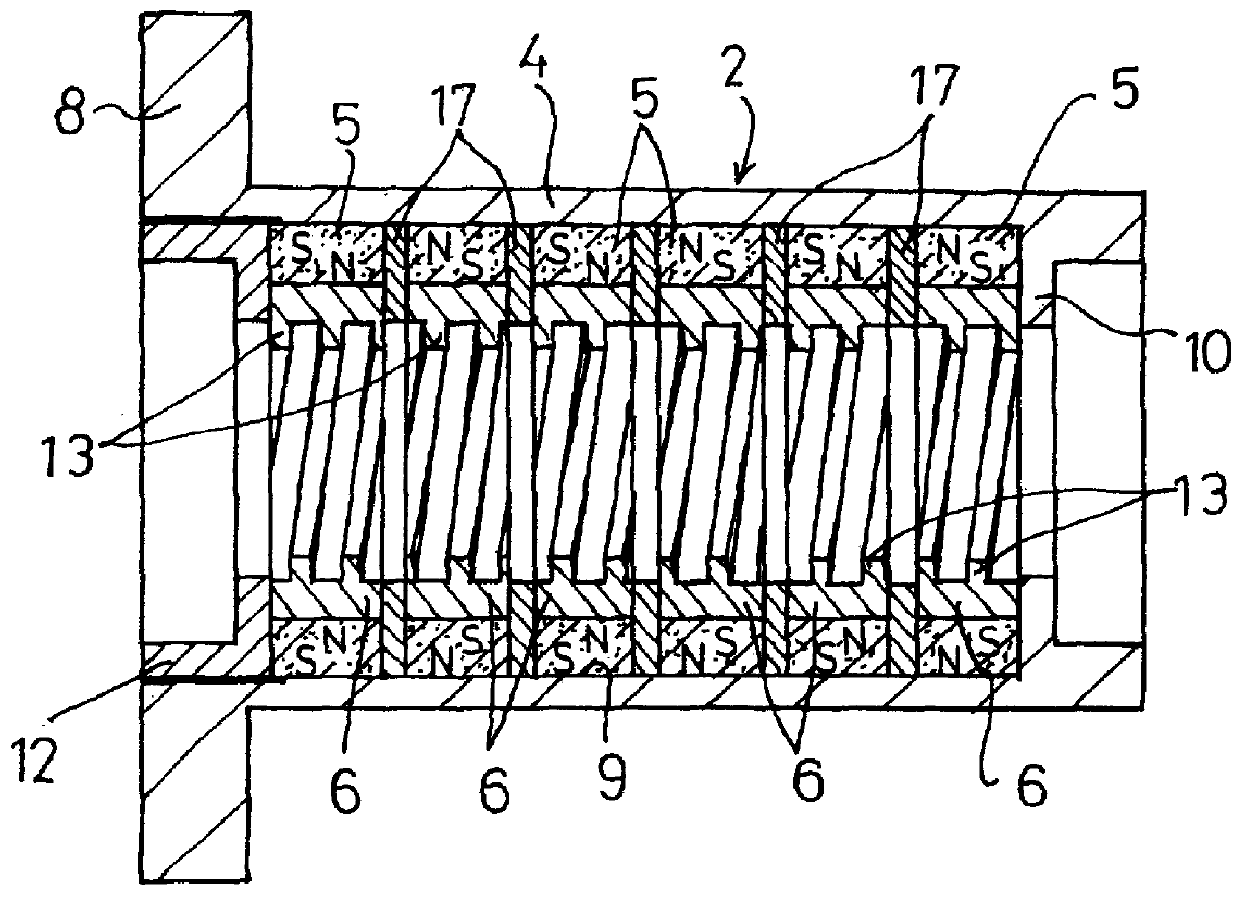
second embodiment

FIG. 4 shows the invention. This magnetic screw comprises pluralities of annular magnets 5 and annular yokes 6 which are concentrically fitted together and axially arranged, with spacers 17 interposed between therebetween. And these magnets 5, yokes 6 and spacers 17 constitute a magnetic unit, which is removably installed in the receiving portion 9 of the housing 4 of magnetic material. In addition, in this embodiment, six magnets 5, six yokes 6 and five spacers 17 are used, but these numbers may be suitably changed according to the magnitude of the required thrust force.

Each magnet 5 is magnetized throughout the circumference such that the radially opposed sides, i.e., the inner and outer peripheral surfaces are formed with magnetic poles of opposite polarities. And these magnets 5 are arranged such that the N- and S-poles axially alternate with each other for both the inner and outer sides.

The housing 4 is made of magnetic material and constitutes an outer yoke so that the magnets...

third embodiment

FIG. 5 shows the invention. In this magnetic screw, the housing 4 of the magnetic nut 2 is made of non-magnetic material, such as stainless steel, and a sleeve 18 of magnetic material for use as a magnetic shield is closely fitted on the outer periphery of the housing 4.

This magnetic nut 2 has a housing 4 made of non-magnetic material. Therefore, as compared with the case of using a magnetic material for the housing 4, leakage of magnetic flux from the magnets 5 to the housing 4 is reduced, making it easier for the magnetic flux from the magnet 5 to move from the yokes 6 to concentrate in the screw shaft 1, so that the thrust force can be prevented from decreasing.

Further, the provision of the sleeve 18 for use as a magnetic shield on the outer side of the housing 4 results in a decrease in the leakage flux which passes from the sleeve 18 to the outside, thus preventing magnetic powders, such as iron powder, from adhering to the outer peripheral surface of the sleeve 18. Therefore, ...


PUM

PropertyMeasurementUnit
thicknessaaaaaaaaaa
polaritiesaaaaaaaaaa
magneticaaaaaaaaaa

Abstract

A magnetic screw having a screw shaft of magnetic material having thread crests formed on the outer peripheral surface thereof, and a magnetic nut fitted on the outer periphery of the screw shaft. The magnetic nut includes annular permanent magnets magnetized with magnetic poles of opposite polarities on opposed sides, and annular yokes disposed such that the annular yokes are magnetically coupled with the magnetic poles of the magnets. The inner peripheral surfaces of the yokes are provided with thread crests corresponding with the thread crests of the screw shaft with a minute gap G defined therebetween such that magnetic circuits are formed between the screw shaft and the magnets through the thread crests of the screw shaft. The magnets are magnetized on their inner and outer radial surfaces with magnetic poles of opposite polarities, and the yokes are fitted in the magnets.

Description

BACKGROUND OF THE INVENTION AND DESCRIPTION OF RELATED ARTSThe present invention relates to a magnetic screw used as a feed device or the like in machine tools and other machines and instruments.Magnetic screws are used as feed devices or the like in machine tools, machines and instruments installed in clean rooms and other various machines and instruments. A magnetic screw comprises a screw shaft of magnetic material having thread crests formed on its outer peripheral surface, and a magnetic nut fitted on the outer periphery of the screw shaft with a minute gap defined therebetween. And when the screw shaft is turned around its axis forward and backward, the magnetic nut is axially reciprocated along the screw shaft by the action of the magnetic coupling between the screw shaft and the magnetic nut.A magnetic screw, unlike a ball screw, does not require the screw shaft and the magnetic nut to be in direct contact with each other, so that it can be used without lubrication and even ...

Claims


Application Information

Patent Timeline
Patent Type & Authority Patents(United States)
IPC IPC(8): F16H25/20H02K49/10H02K49/00F16H25/24F16H49/00H01F7/02
CPCH02K49/102F16H25/24Y10T74/19712Y10S74/04
Inventor FURUSE, DECEASED, AKIRAKUNIHIRO, KAZUTOKITAI, NOBUYUKIHASHIMOTO, JUNICHI
Owner KOYO MASCH IND CO LTD
Why Eureka
Try Eureka