Four-Wall Turbine Airfoil with Thermal Strain Control for Reduced Cycle Fatigue

a four-wall turbine and thermal strain control technology, applied in the field of turbine airfoils, can solve problems such as limitations of low cycle fatigue (lcf)

Inactive Publication Date: 2011-09-29
SIEMENS ENERGY INC
View PDF22 Cites 83 Cited by
  • Summary
  • Abstract
  • Description
  • Claims
  • Application Information

AI Technical Summary

Problems solved by technology

However, differential thermal expansion between the hot outer walls and the cooler inner walls can cause Low Cycle Fatigue (LCF) limitations for reasons later described.

Method used


Image

  • Four-Wall Turbine Airfoil with Thermal Strain Control for Reduced Cycle Fatigue
  • Four-Wall Turbine Airfoil with Thermal Strain Control for Reduced Cycle Fatigue
  • Four-Wall Turbine Airfoil with Thermal Strain Control for Reduced Cycle Fatigue

Examples


Embodiment Construction

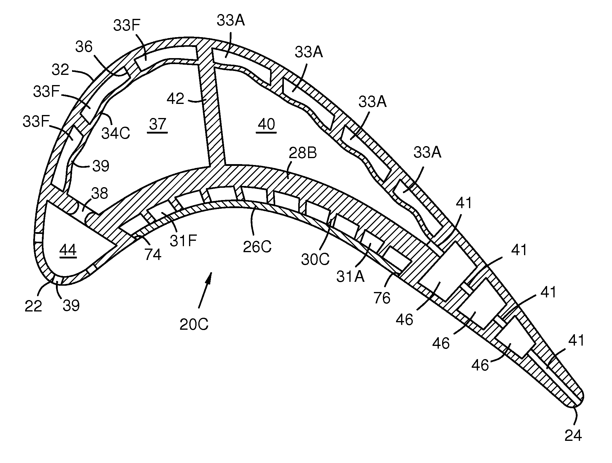
[0015]The invention reduces and relocates stress on a 4-wall turbine airfoil by controlling the thermal expansion mismatch between the relatively hotter outer walls and the relatively cooler inner walls to reduce low cycle fatigue (LCF) in the airfoil.

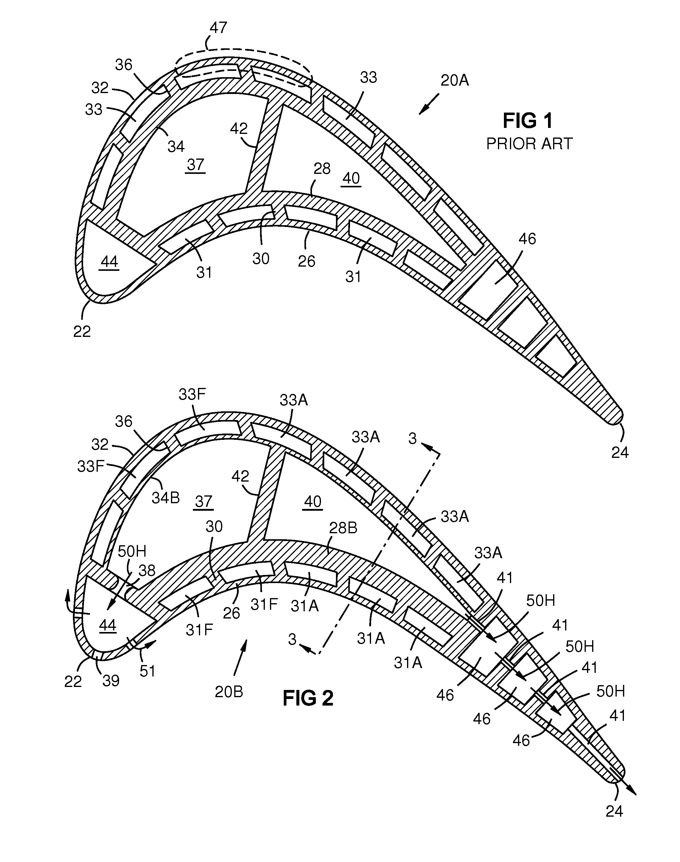
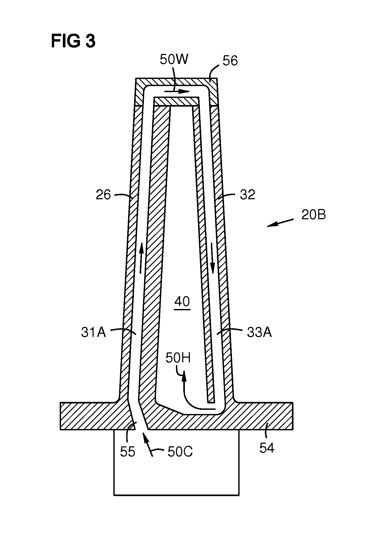
[0016]FIG. 1 shows a known construction of a 4-wall airfoil 20A. The purpose of a 4-wall airfoil is to provide near-wall cooling, in which the cooling air flows in channels 31, 33 adjacent to the outer walls 26, 32 of the airfoil. The cooling channels 31, 33 are formed between the double walls 26, 28 and 32, 34. Near-wall cooling is advantageous because the cooling air is in close proximity of the hot outer surfaces of the airfoil, and the resulting heat transfer coefficients are high due to the high flow velocity achieved by restricting the flow through narrow channels.

[0017]The airfoil 20A of FIG. 1 has a leading edge 22, a trailing edge 24, a pressure side outer wall 26, a pressure side inner wall 28, pressure side ribs 30, pressure...


PUM


Abstract

A turbine airfoil (20B) with a thermal expansion control mechanism that increases the airfoil camber (60, 61) under operational heating. The airfoil has four-wall geometry, including pressure side outer and inner walls (26, 28B), and suction side outer and inner walls (32, 34B). It has near-wall cooling channels (31F, 31A, 33F, 33A) between the outer and inner walls. A cooling fluid flow pattern (50C, 50W, 50H) in the airfoil causes the pressure side inner wall (28B) to increase in curvature under operational heating. The pressure side inner wall (28B) is thicker than walls (26, 34B) that oppose it in camber deformation, so it dominates them in collaboration with the suction side outer wall (32), and the airfoil camber increases. This reduces and relocates a maximum stress area (47) from the suction side outer wall (32) to the suction side inner wall (34B, 72) and the pressure side outer wall (26).

Description

STATEMENT REGARDING FEDERALLY SPONSORED DEVELOPMENT[0001]Development for this invention was supported in part by Contract No. DE-FC26-05NT42644, awarded by the United States Department of Energy. Accordingly, the United States Government may have certain rights in this invention.FIELD OF THE INVENTION[0002]This invention is related generally to turbine airfoils, and more particularly to hollow turbine airfoils such as blades and vanes with internal cooling channels for passing fluids such as air to cool the airfoils.BACKGROUND OF THE INVENTION[0003]Gas turbine engines include a compressor for compressing air, a combustor for mixing the compressed air with fuel and igniting the mixture, and a turbine blade and vane assembly for producing power. Combustors operate at high temperatures that may exceed 2,500 degrees Fahrenheit. Typical turbine combustor configurations expose the turbine vane and blade assemblies to these high temperatures. Turbine vanes and blades must be made of materi...

Claims


Application Information

Patent Timeline
Patent Type & Authority Applications(United States)
IPC IPC(8): F01D5/18
CPCF01D5/148F05D2300/50212F01D5/187
Inventor CAMPBELL, CHRISTIAN X.
Owner SIEMENS ENERGY INC
Why Eureka
Try Eureka