Double Sealing Labyrinth Chamber for Use With a Downhole Electrical Submersible Pump

a technology of electrical submersible pumps and labyrinth chambers, which is applied in the direction of pumping, positive displacement liquid engines, machines/engines, etc., can solve the problems of wellbore fluid breaching seals and leakage into the motor of the esp, and conventional seal sections have not proved completely effective in preventing environmental contamination of the motor

Inactive Publication Date: 2011-09-29
BAKER HUGHES INC
View PDF8 Cites 33 Cited by
  • Summary
  • Abstract
  • Description
  • Claims
  • Application Information

AI Technical Summary

Benefits of technology

[0007]Disclosed herein is an electrical submersible pump assembly disposable within a wellbore. In one example, the electrical submersible pump assembly includes a motor, a pump coupled to the motor, a seal section housing between the pump and the motor, upper and lower guide members in the seal section housing, each having a central passage therethrough, defining a chamber in the seal section housing, an equalizing passage leading from the chamber to the motor, a shaft extending between the pump and the motor and through the central passages in the upper and lower guide members in the seal section housing, an upper seal between the passage of the upper guide member that seals around the shaft and seals well fluid from the chamber, and an inner labyrinth seal assembly circumscribing the shaft between the upper and lower guide members and comprising a looping flow path with an upper end in fluid communication with fluid in the central passage between the upper seal and an upper port in fluid communication with the chamber, so as to prevent well fluid that may leak past the upper seal from entering the pressure equalizing passage. An outer labyrinth seal assembly may be included with the electrical submersible pump assembly, where the outer labyrinth seal assembly has a looping flow path in the chamber with a first end in fluid commun...

Problems solved by technology

One hazard of high ESP housing pressure differentials is the wellbore fluid could breach seals and leak into the motor of...

Method used


Image

  • Double Sealing Labyrinth Chamber for Use With a Downhole Electrical Submersible Pump
  • Double Sealing Labyrinth Chamber for Use With a Downhole Electrical Submersible Pump
  • Double Sealing Labyrinth Chamber for Use With a Downhole Electrical Submersible Pump

Examples


Embodiment Construction

[0017]The present invention will now be described more fully hereinafter with reference to the accompanying drawings in which exemplary embodiments of the invention are shown. This invention may, however, be embodied in many different forms and should not be construed as limited to the illustrated embodiments set forth herein; rather, these embodiments are provided so that this disclosure will be through and complete, and will fully convey the scope of the invention to those skilled in the art. Like numbers refer to like elements throughout.

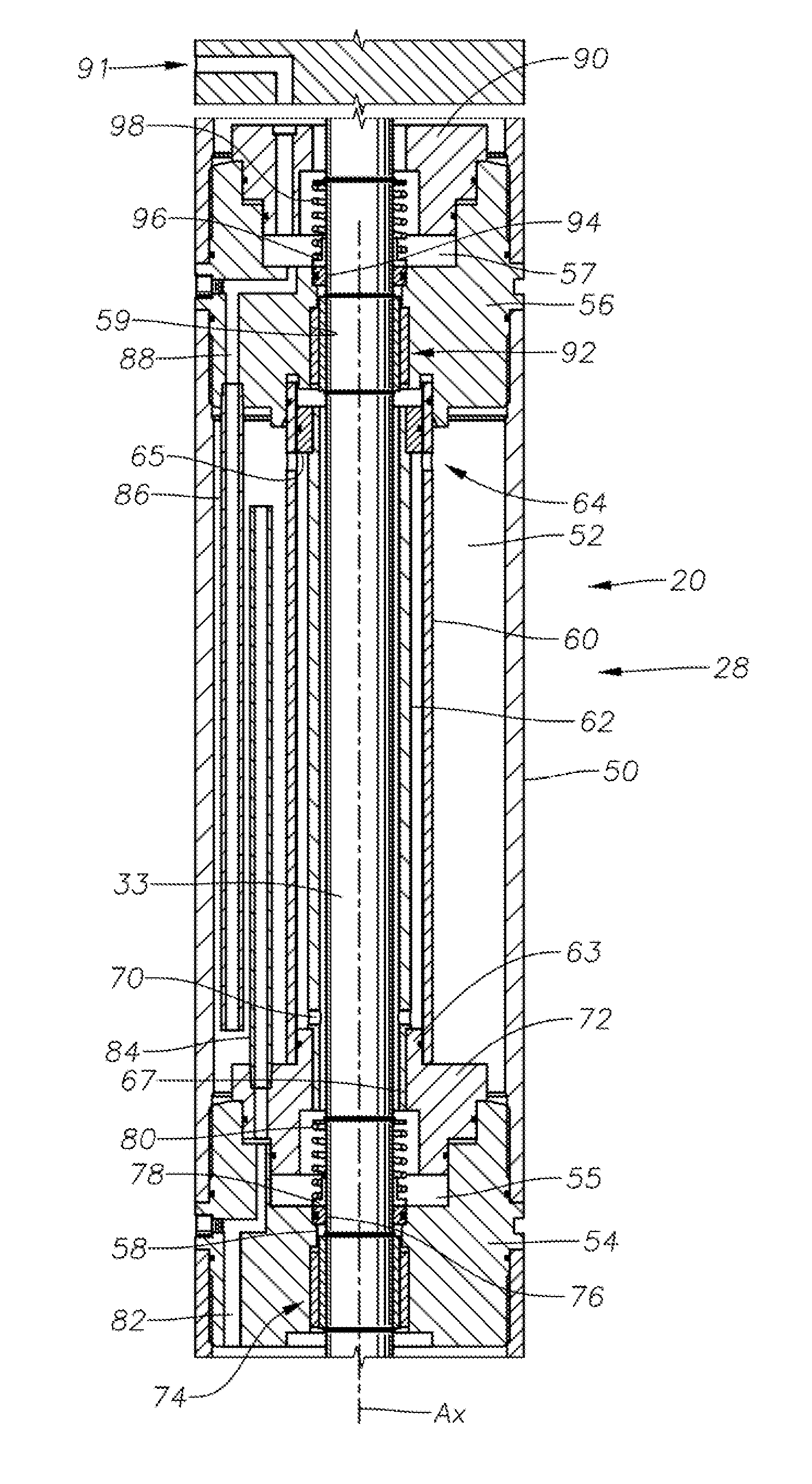
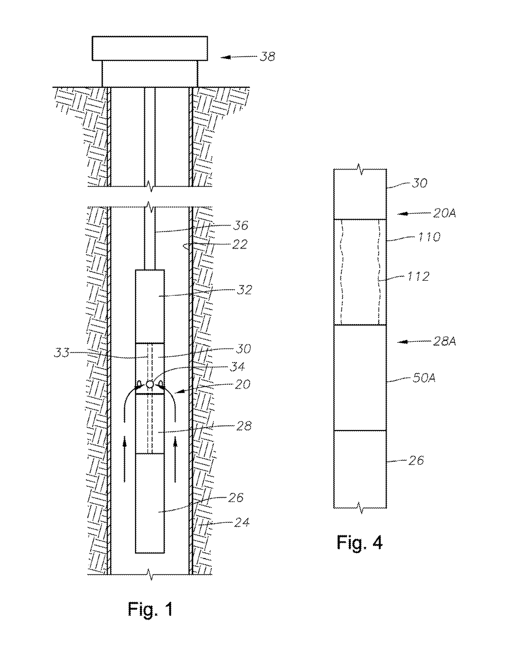
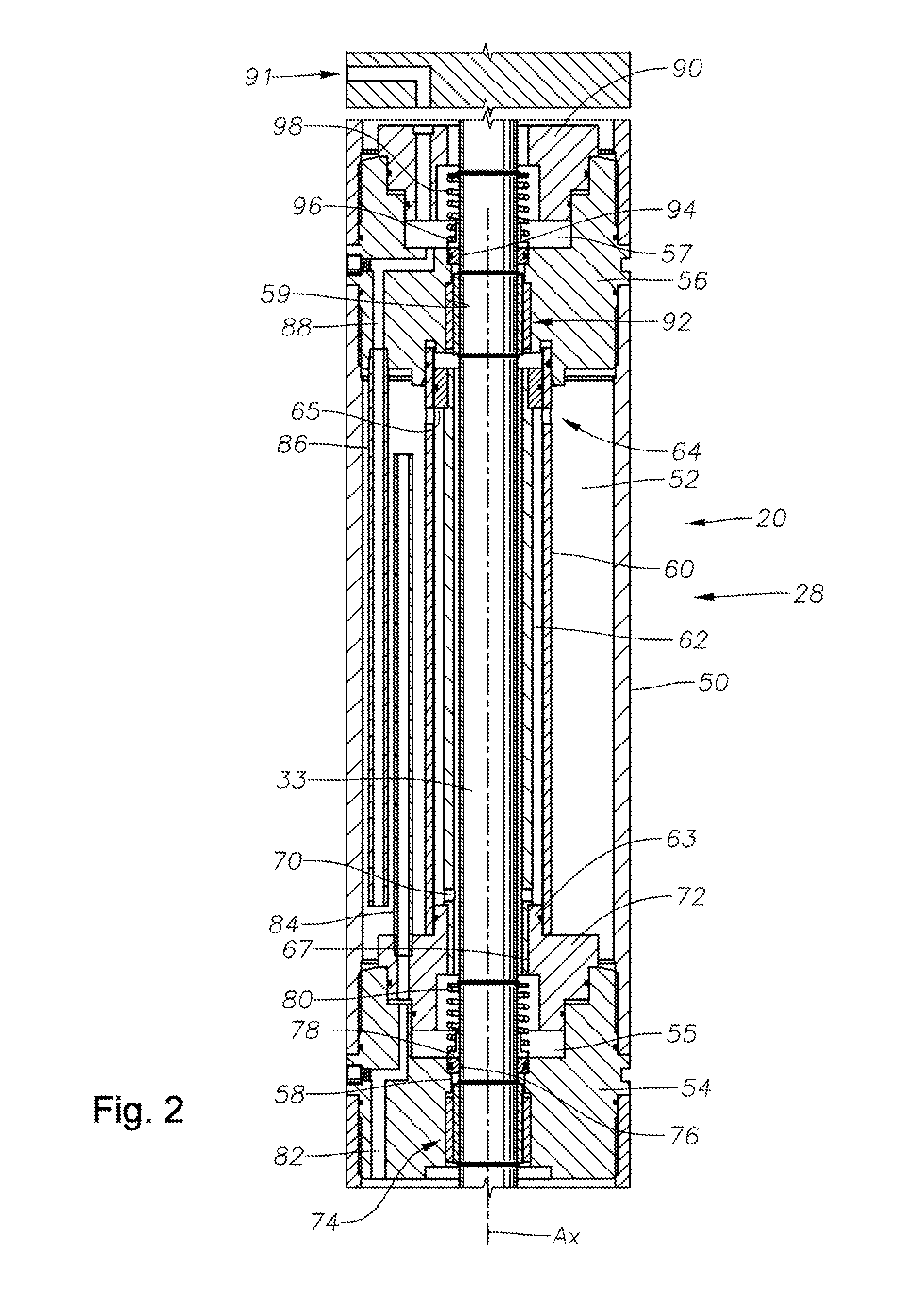
[0018]Referring now to FIG. 1 an example of an electrical submersible pumping system 20 (ESP) is shown in side view disposed in a sectional view of a wellbore 22. In this example the wellbore 22 intersects a subterranean formation 24. The ESP 20 of FIG. 1 includes on its lower end a motor 26, a seal section 28 attached to an upper end of the motor 26, and stacked above the seal section 28 is an optional separator 30. The ESP 20 further includes a...


PUM


Abstract

A labyrinth seal assembly for an electrical submersible pumping system that communicates downhole pressure to a pump motor while sealing wellbore fluids from the motor. The labyrinth seal assembly includes a chamber circumscribing a pump shaft, labyrinth tubes, upper and lower shaft seals, and inner and outer guide tubes coaxially circumscribing the shaft. One labyrinth tube has an end in fluid communication with the wellbore fluid and another has an end in fluid communication with the pump motor. The labyrinth tubes extend into the chamber from opposite directions and each have an opening distal from where they enter the chamber. A port is provided in the inner guide tube distal from the upper shaft seal, and a port in the outer guide tube is provided proximate the upper shaft seal. Thus a labyrinth path is provided between the upper shaft seal and the chamber.

Description

BACKGROUND[0001]1. Field of Invention[0002]The present disclosure relates in general to submersible well pumps, and in particular to seal assemblies used in combination with the motors that drive submersible well pumps.[0003]2. Background of the Invention[0004]In oil wells and other similar applications in which the production of fluids is desired, a variety of fluid lifting systems have been used to pump the fluids to surface holding and processing facilities. It is common to employ various types of downhole pumping systems to pump the subterranean formation fluids to surface collection equipment for transport to processing locations. One such conventional pumping system is a submersible pumping assembly which is supported immersed in the fluids in the wellbore. The submersible pumping assembly includes a pump and a motor to drive the pump to pressurize and pass the fluid through production tubing to a surface location. A typical electrical submersible pump assembly (“ESP”) include...

Claims


Application Information

Patent Timeline
IPC IPC(8): F04B17/03
CPCF04B17/03
Inventor MERILL, DAN
Owner BAKER HUGHES INC
Why Eureka
Try Eureka