Submerged combustion melter

a technology of submerged combustion and melter, which is applied in the direction of lighting and heating apparatus, tank furnaces, furnaces, etc., can solve the problems of low co and unburned hydrocarbon emissions, limited practical application, and reduced flame temperature, so as to increase melter efficiency and reduce hot spots in the melt and on the melt chamber walls. , the effect of reducing the temperature of the mel

Inactive Publication Date: 2011-09-29
GAS TECH INST
View PDF14 Cites 148 Cited by
  • Summary
  • Abstract
  • Description
  • Claims
  • Application Information

AI Technical Summary

Benefits of technology

[0011]These and other objects of this invention are addressed by a submerged combustion melter having a plurality of side walls, a bottom wall adjacent to the side walls, and a top wall adjacent to the side walls, which walls collectively enclose a melting chamber. The bottom wall forms a plurality of openings, each of which is adapted to receive a submerged combustion burner. Each of the submerged combustion burners is positioned at least 4 inches from t

Problems solved by technology

Combustion in the melt reduces flame temperature, which results in extremely low NOx emissions compared with other combustion processes, and complete combustion within the melt results in low CO and unburned hydrocarbon emissions.
While submerged combustion melting is known, practical applications have been limited due to a lack of practical ways to address several issues relating to the technology.
These issues include: a) poorly designed burner firing patterns which can lead to the bypass of feed particles before they are fully melted; b) poorly placed burners which can produce undesirable hot

Method used


Image

  • Submerged combustion melter
  • Submerged combustion melter
  • Submerged combustion melter

Examples


Embodiment Construction

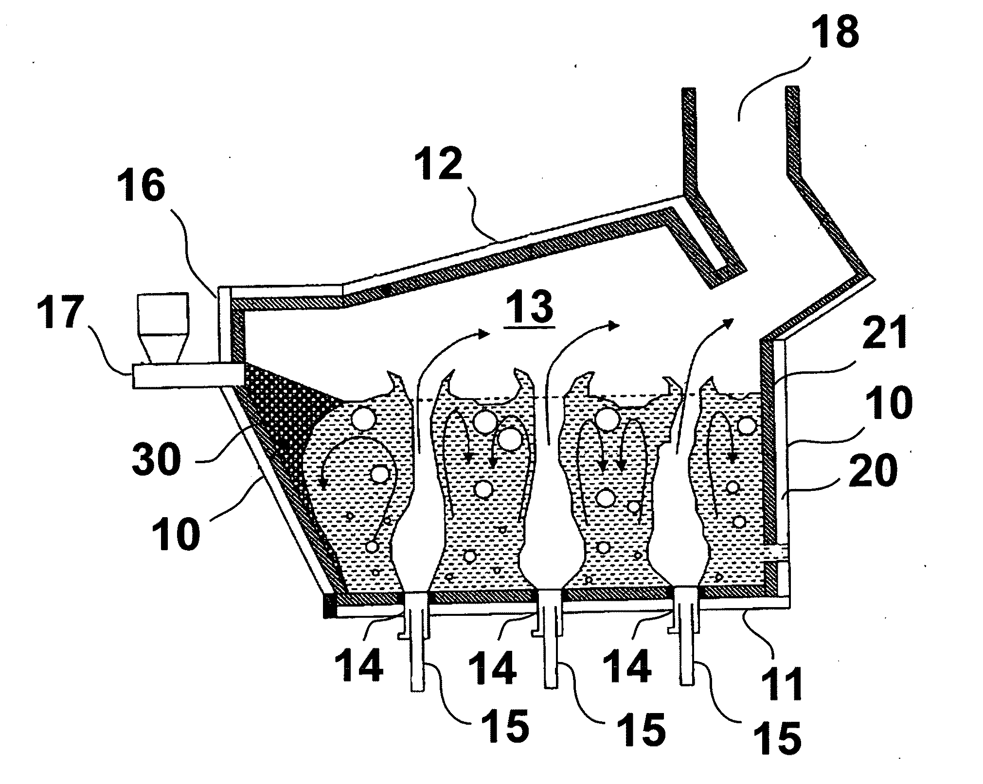
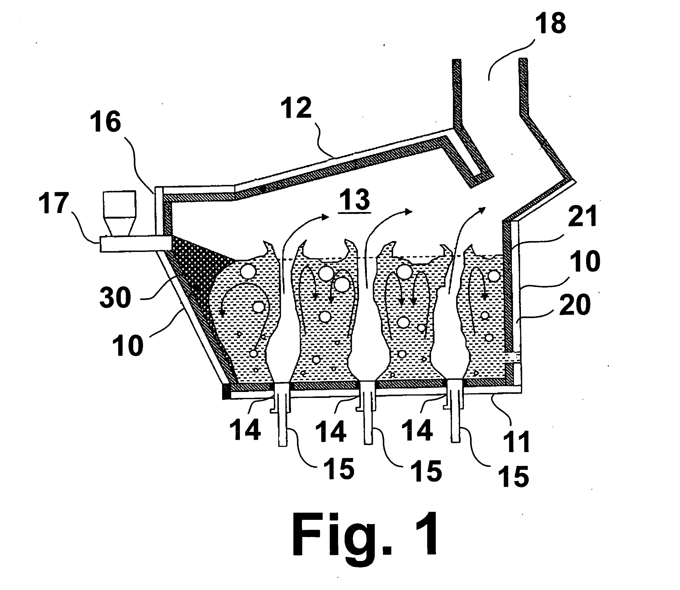
[0019]FIG. 1 is a lateral cross-sectional view of a submerged combustion melting apparatus in accordance with one embodiment of this invention. The apparatus comprises a plurality of side walls 10, a bottom wall 11 adjacent the side walls, and a top wall 12 adjacent the side walls, which walls collectively enclose a melting chamber 13. The bottom wall 11 forms a plurality of openings 14, each of which is adapted to receive a submerged combustion burner 15. As melter size is increased, the number of burner rows amend number of burners in each row is increased. Connected with one side wall, referred to herein as a feeder side wall 16, is a feeder 17 through which raw materials to be melted are introduced into the melting chamber 13. The apparatus further comprises a flue gas exhaust opening 18 through which combustion product gases are expelled from the melting chamber.

[0020]In accordance with one embodiment of this invention, the walls of the submerged combustion apparatus are constr...


PUM

PropertyMeasurementUnit
Thicknessaaaaaaaaaa
Thicknessaaaaaaaaaa
Angleaaaaaaaaaa

Abstract

A submerged combustion melter having a plurality of side walls, a bottom wall adjacent the side walls, and a top wall adjacent the side walls, the walls collectively enclosing a melting chamber, and the bottom wall forming a plurality of openings, each of which is adapted to receive a submerged combustion burner. Each of the submerged combustion burners is positioned at least 4 inches from the side walls, at least twice as far apart from each other as the distance between the submerged combustion burners and the side walls, and less than or equal to about 20 inches apart.

Description

[0001]The U.S. Government has a paid-up license in this invention and the right in limited circumstances to require the patent owner to license others on reasonable terms as provided for by the terms of Contract No. DE-FC36-03GO13092 awarded by the U.S. Department of Energy.BACKGROUND OF THE INVENTION [0002]This invention relates to a process and apparatus for submerged combustion melting.[0003]Submerged combustion melting is an advanced melting technology for economically and cleanly producing homogeneous mineral melts. Numerous industrially and environmentally useful melts can be produced by submerged combustion melting at operating and capital cost advantages compared to other melting techniques. Submerged combustion melting provides a combination of features not available in any other melting technology.[0004]In submerged combustion melting, burners fire natural gas or other fuel gas and oxidant, i.e. air, oxygen-enriched air, or oxygen, from directly under and into a bath of ma...

Claims


Application Information

Patent Timeline
IPC IPC(8): F27B3/22
CPCF27B3/205F27B17/00C03B5/2356C03B5/04C03B2211/22C03B2211/70C03B3/00C03B5/44
Inventor RUE, DAVID M.ARONCHIK, GRIGORY I.KHINKIS, MARK J.KUNC, WALTER
Owner GAS TECH INST
Why Eureka
Try Eureka