Arrangement and method for detecting and/or locating a magnetic material in a region of action

a magnetic material and arrangement technology, applied in the field of arrangement for detecting and/or locating magnetic materials in the region of action, can solve the problems of requiring very long calibration procedures, unable to identify simple mathematical transformations to reconstruct images from acquired data, and unable to solve the problem of inverse reconstruction, etc., to achieve the effect of less storage space and less time for acquisition

Active Publication Date: 2011-09-29
KONINKLIJKE PHILIPS ELECTRONICS NV
View PDF2 Cites 6 Cited by
  • Summary
  • Abstract
  • Description
  • Claims
  • Application Information

AI Technical Summary

Benefits of technology

[0006]It is an object of the present invention to provide an arrangement and a method for detecting and / or locating a magnetic material in a region of action by which less time for acquisition of the system function data of the system function and / or for image reconstruction is required and / or by which less storage space for storing the system function data of the system function is needed.

Problems solved by technology

However, in contrast to established imaging modalities like MRI and CT, no simple mathematical transform has yet been identified to reconstruct images from the acquired data.
This calibration procedure requires very long acquisition times and furthermore provides a system function that is contaminated with noise.
Due to the large size of the system function matrix, solving the inverse reconstruction problem is also quite time-consuming and requires large amounts of computer memory.

Method used


Image

  • Arrangement and method for detecting and/or locating a magnetic material in a region of action
  • Arrangement and method for detecting and/or locating a magnetic material in a region of action
  • Arrangement and method for detecting and/or locating a magnetic material in a region of action

Examples


first embodiment

[0129]The first embodiment according to the present invention which makes use of spatial symmetries (cf. FIGS. 17, 18) essentially requires the following steps for reconstruction:

1. Using obvious mirror symmetries (cf. FIG. 17)

a. Measure reduced system function at selected positions (e.g. one quadrant / octant or interleaved positions).

b. Generate full system function matrix by mirror operations.

c. Do standard reconstruction with full matrix.

2. Using a sparsity transform along the spatial directions (cf. FIG. 18)

a. Measure system function at selected positions to obtain coefficients for the function set used to expand the spatial distribution (e.g. Chebyshev coefficients).

b. Since the spatial distribution can be approximated by fewer components in the transform space k, the system function is represented by a sparse matrix and, if the true resolution is smaller than the voxel resolution, the spatial dimension of the vector is smaller than in real space x.

c. Solve sparse inverse proble...

second embodiment

[0130]The second embodiment according to the present invention which makes use of redundant frequency components (cf. FIG. 19) essentially requires the following steps for reconstruction:

1. Take full or spatially reduced system function matrix.

2. Identify frequency components (rows) with identical spatial pattern (e.g. from theoretical considerations).

3. Sum these components in system function matrix and measurement vector.

4. Invert reduced problem to get image c(x).

[0131]While the invention has been illustrated and described in detail in the drawings and foregoing description, such illustration and description are to be considered illustrative or exemplary and not restrictive; the invention is not limited to the disclosed embodiments. Other variations to the disclosed embodiments can be understood and effected by those skilled in the art in practicing the claimed invention, from a study of the drawings, the disclosure, and the appended claims.

[0132]In the claims, the word “comprisi...


PUM


Abstract

In Magnetic Particle Imaging (MPI) the reconstruction requires the knowledge of a so called system function. This function describes the relation between spatial position and frequency response. For reasonable resolutions and field of views the system function becomes quite large, resulting in large acquisition times for the system function and high memory demand during reconstruction. The present invention proposes to reduce the size of the system function matrix by making use of structural properties of the matrix. Such properties are, for instance, spatial symmetries reducing the number of columns and identical responses at different frequencies reducing the number of rows. In other embodiments the matrix can be transformed to a sparse representation using appropriate base functions.

Description

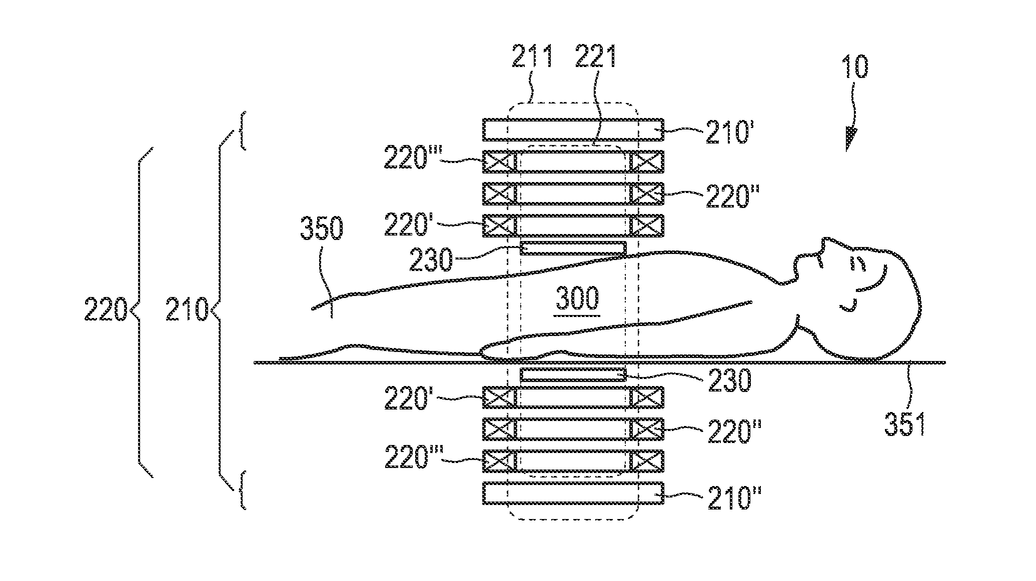
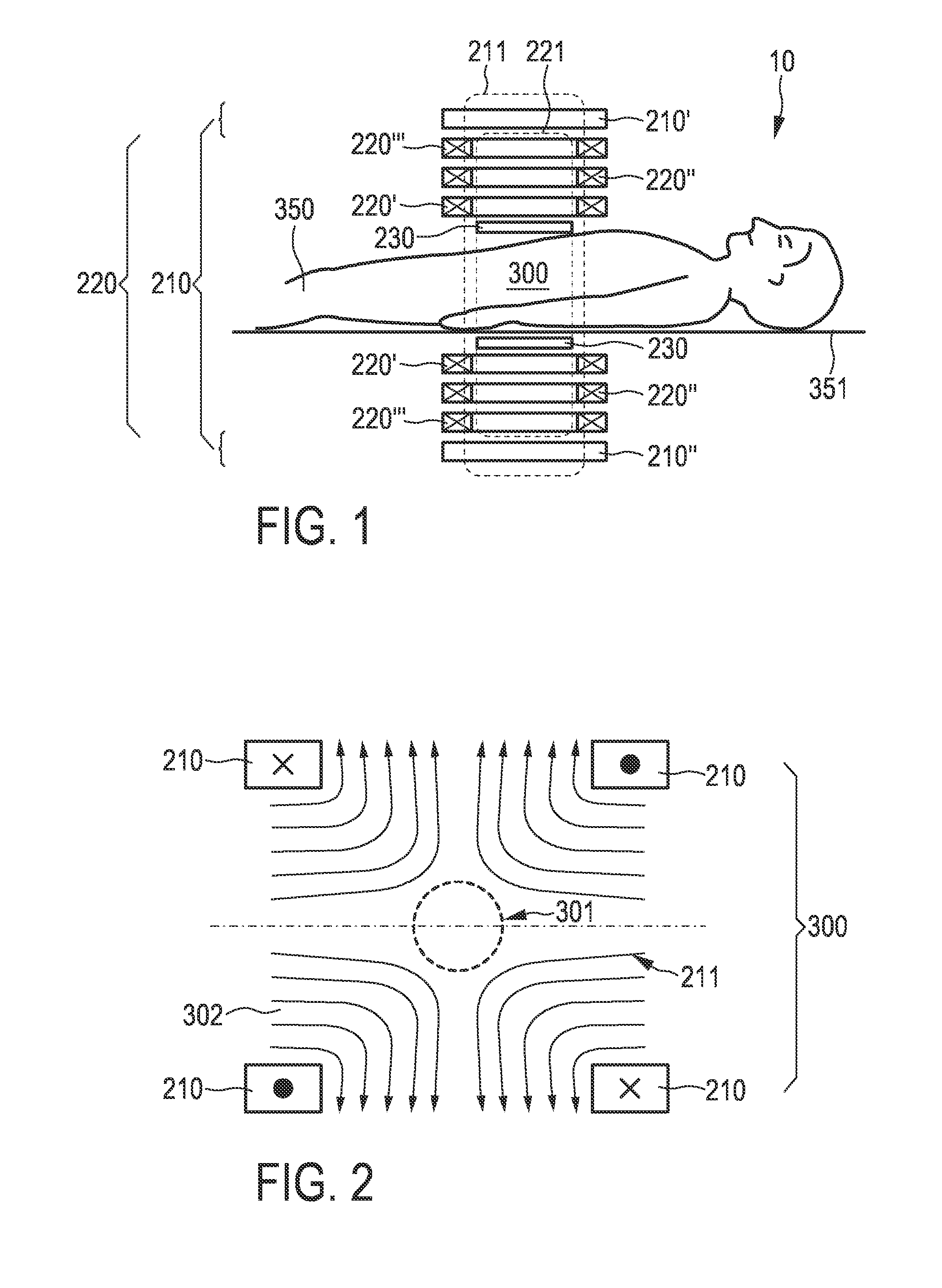
FIELD OF THE INVENTION[0001]The present invention relates to an arrangement for detecting and / or locating a magnetic material in a region of action. The present invention relates further to a corresponding method and to a computer program for control of the arrangement.BACKGROUND OF THE INVENTION[0002]An arrangement of this kind is known from German patent application DE 101 51 778 A1. In the arrangement described in that publication, first of all a magnetic field having a spatial distribution of the magnetic field strength is generated such that a first sub-zone having a relatively low magnetic field strength and a second sub-zone having a relatively high magnetic field strength are formed in the examination zone. The position in space of the sub-zones in the examination zone is then shifted, so that the magnetization of the particles in the examination zone changes locally. Signals are recorded which are dependent on the magnetization in the examination zone, which magnetization h...

Claims


Application Information

Patent Timeline
Patent Type & Authority Applications(United States)
IPC IPC(8): A61B5/05
CPCA61B5/0515A61B5/05
Inventor RAHMER, JURGEN ERWINWEIZENECKER, JUERGENGLEICH, BERNHARD
Owner KONINKLIJKE PHILIPS ELECTRONICS NV
Why Eureka
Try Eureka