
Vibro-Acoustical Body Support

Inactive Publication Date: 2011-09-29
VANDENBELT RUDY A +2
View PDF5 Cites 9 Cited by
  • Summary
  • Abstract
  • Description
  • Claims
  • Application Information

AI Technical Summary

Benefits of technology

[0009]The low-frequency transducer has an aperture size much smaller than that of the diaphragm. When the diaphragm is set in motion, it transfers energy directly to the user over an area much larger than the aperture size of the of the low-frequency transducer thereby providing low-frequency therapy at comparatively-low cost.
[0013]The sounds provided by the audio source may be streamed or prerecorded, the prerecorded sounds may be provided on internal and / or by external memory, and may be played through speakers and / or headphones. In the presently preferred and exemplary chair topper embodiment, the audio sounds are in MP3 format stored on internal memory and are grouped to provide user-selectable “sleep,”“relaxation,”“energization,” and “stress relief” sounds. The intensity of the low-frequency source may advantageously be adjusted by the user between predetermined minimum and maximum values. Advantageously and desirably, the control input for audio selection and for intensity of low-frequency vibrational energy conveniently is provided on a hand-held controller that may be stowed in the chair topper when not in use. Alternately, the controls may be built into the chair topper.

Problems solved by technology

However, not only are Skille's specially designed chairs and beds costly, and comparatively difficult to manufacture, but the utility of Skille's low-frequency energy source is limited by the direct through air coupling of its low-frequency, closed box loudspeakers; the air attenuates the low-frequency energy.
The utility of Skille's low-frequency energy source is also limited by the loudspeaker of its low-frequency, closed box loudspeakers.
The larger the aperture size the larger the area treated but the greater the cost and the more difficult it is to integrate into chairs and bedding.
An array of smaller diameter loudspeakers may be used, but the cost multiplies by the number of loudspeakers arrayed.

Method used


Image

  • Vibro-Acoustical Body Support
  • Vibro-Acoustical Body Support
  • Vibro-Acoustical Body Support

Examples


Embodiment Construction

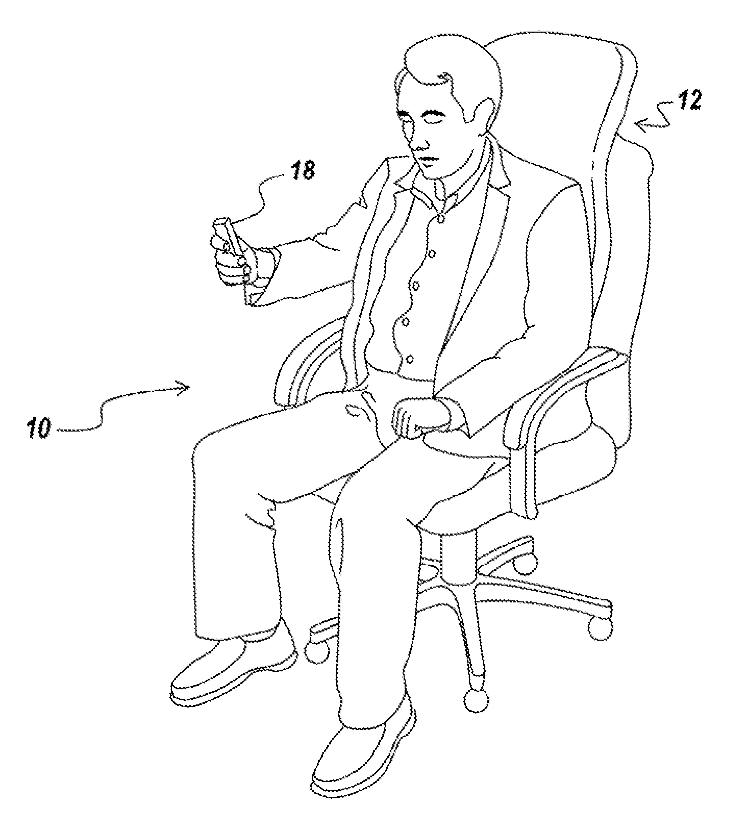
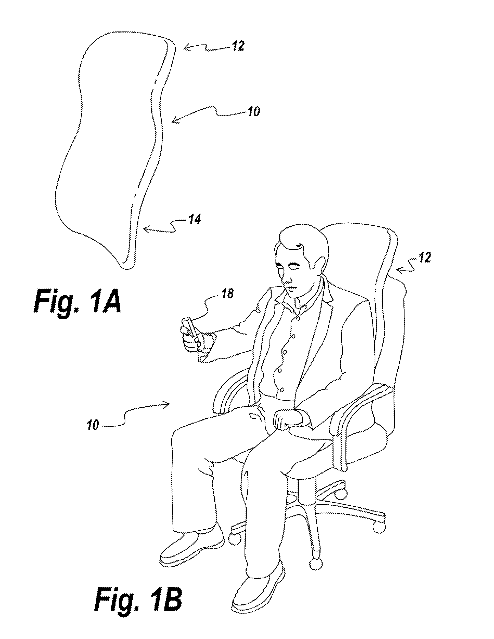
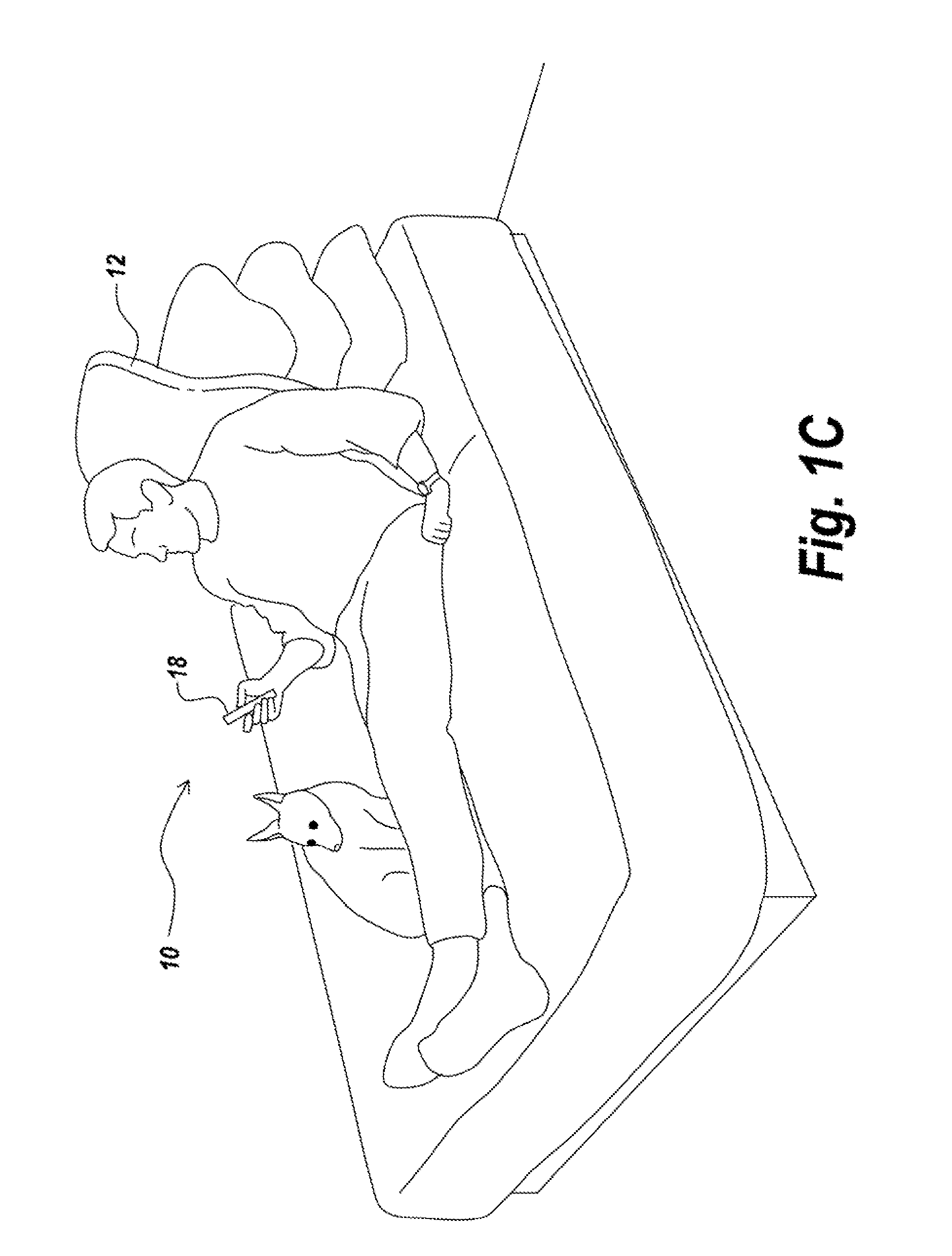
[0023]Referring now to FIGS. 1A, 1B and 1C, generally designated at 10 are pictorial views of a vibro-acoustical chair topper in accord with the present invention. The chair topper 10 has a slim profile taller and wider than it is thick by which it is adapted for removable placement between a user and a seat-back as illustrated in the FIGS. 1B, 1C.

[0024]The chair topper 10 includes an upper, head rest area generally designated 12 and a lower, back rest area generally designated 14. The upper, head rest area 12 is provided with a source of acoustic energy to be described and the lower, back rest area 14 of the chair topper 10 is provided with a source of low-frequency vibrational energy to be described. A hand-held controller 18 allows the user to listen to audio provided via the acoustic source and to concurrently experience vibrational energy provided via the source of low-frequency vibrational energy in various user settable and selectable vibro-acoustical modes to be described.

[0...


PUM


Abstract

A vibro-acoustical body support includes sources of audio and of low-frequency vibrational energy carried by or coupled to a chassis. The source of audio preferably includes an MP3 player and stereo speakers and / or headphones. The source of low-frequency vibrational energy includes a resonating chamber having a resonant wall provided by a diaphragm and a low-frequency transducer attached to the diaphragm that freely extends into the resonating chamber. In one presently preferred and exemplary chair topper embodiment, the chassis has an orthopedic S-shape and the diaphragm is arranged as a back supporting resonant lumbar plate.

Description

FIELD OF THE INVENTION[0001]This invention is drawn to the field of kinesotherapy, and more particularly, to an improved vibro-acoustical body support.BACKGROUND OF THE INVENTION[0002]U.S. Pat. No. 5,101,810, issued Apr. 7, 1992 to Skille et al., incorporated herein by reference, discloses apparatus and method for therapeutic application of vibro-acoustical energy to the human body.[0003]Skille's invention, variously embodied in specially designed chairs and beds, includes audio speakers for playing music, together with a low-frequency loudspeaker. The low-frequency loudspeaker, contained in a closed box built into the chair or bed, provides low-frequency vibrational energy directly through the air to the human body. The sounds of the audio speakers and the low-frequency vibrations of the loudspeaker act in combination on the user to provide vibro-acoustical therapy whose physical and psychical character depends on the parameters selected for the low-frequency vibrations and on the ...

Claims


Application Information

Patent Timeline
IPC IPC(8): A61H1/00
CPCA47C7/425A47C20/027A61H2205/081A61H2201/5035A61H2201/5048A61H23/0236
Inventor VANDENBELT, RUDY A.BAILEY, MATTHEW T.R.COWIE, ROSS L.
Owner VANDENBELT RUDY A
Learn More