Method and apparatus for ultrasonic testing of weld zones

a technology of ultrasonic testing and weld zone, which is applied in the direction of analyzing fluids using sonic/ultrasonic/infrasonic waves, instruments, and specific gravity measurements, etc. it can solve the problems of low inspection efficiency of x-ray inspection, deterioration of quality of weld zone, and flaws that occur in the weld zone of test objects. it can stabilize the flaw detection accuracy and accurately detect the flaws.

Active Publication Date: 2011-10-06
NIPPON STEEL CORP
View PDF7 Cites 11 Cited by
  • Summary
  • Abstract
  • Description
  • Claims
  • Application Information

AI Technical Summary

Benefits of technology

[0060]According to this preferred configuration, it is possible to cause a coupling medium to accumulate inside the coupling medium reservoir part surrounding a space between the ultrasonic probe and the weld zone, and what is more, because the coupling medium reservoir part having a bellows structure expands and contracts in such a manner as to adapt itself to the bead shape of the weld zone, the ultras...

Problems solved by technology

Depending on welding methods and welding conditions, various flaws occur in a weld zone of a test object, such as a welded pipe.
These flaws cause a quality deterioration of the weld zone.
However, X-ray inspection has problems of low inspection efficiency, high equipment cost, and the like.
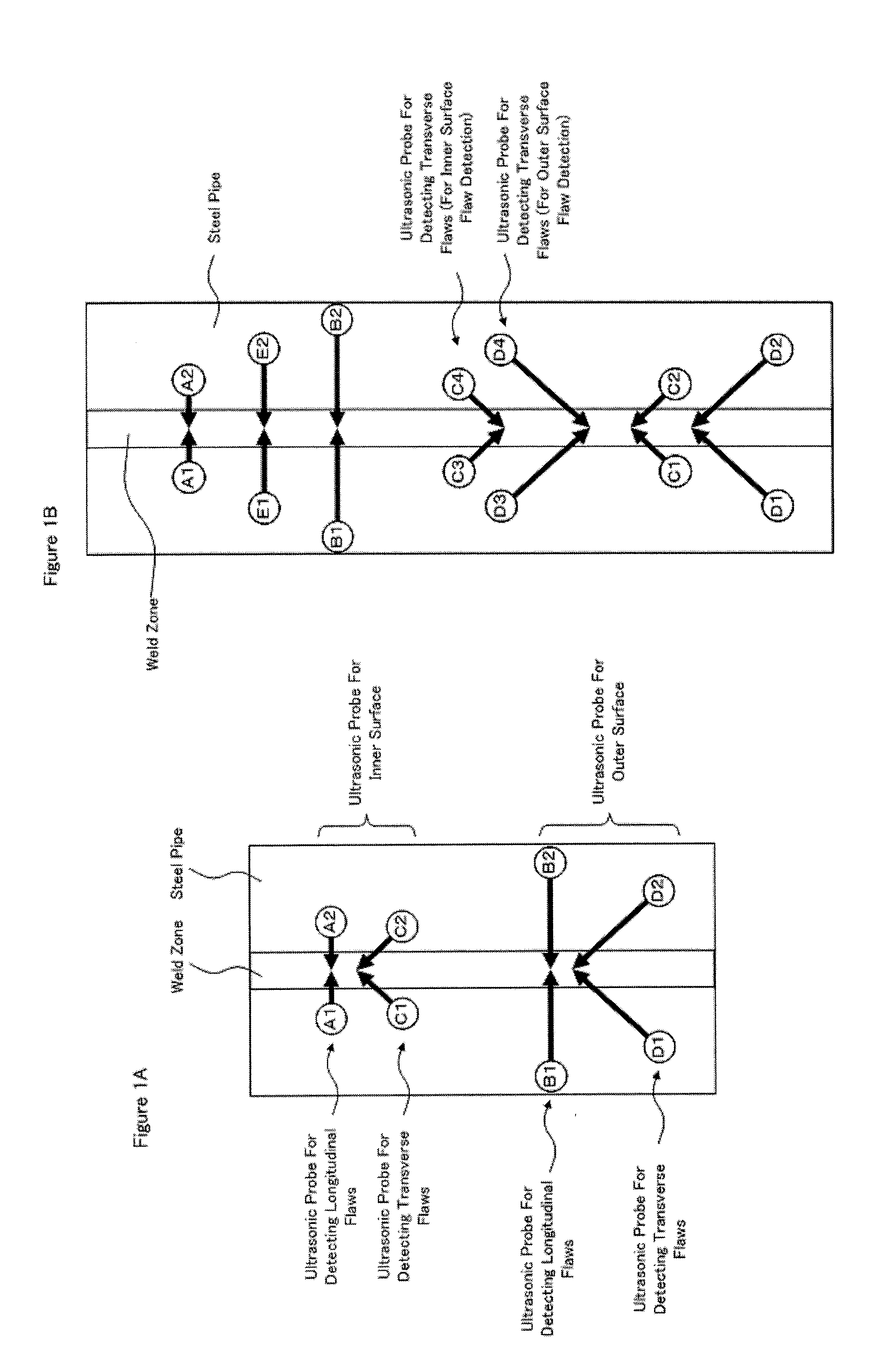
However, ultrasonic testing by ultrasonic probes of general K-form arrangement as shown in FIG. 1A has a problem as described below.
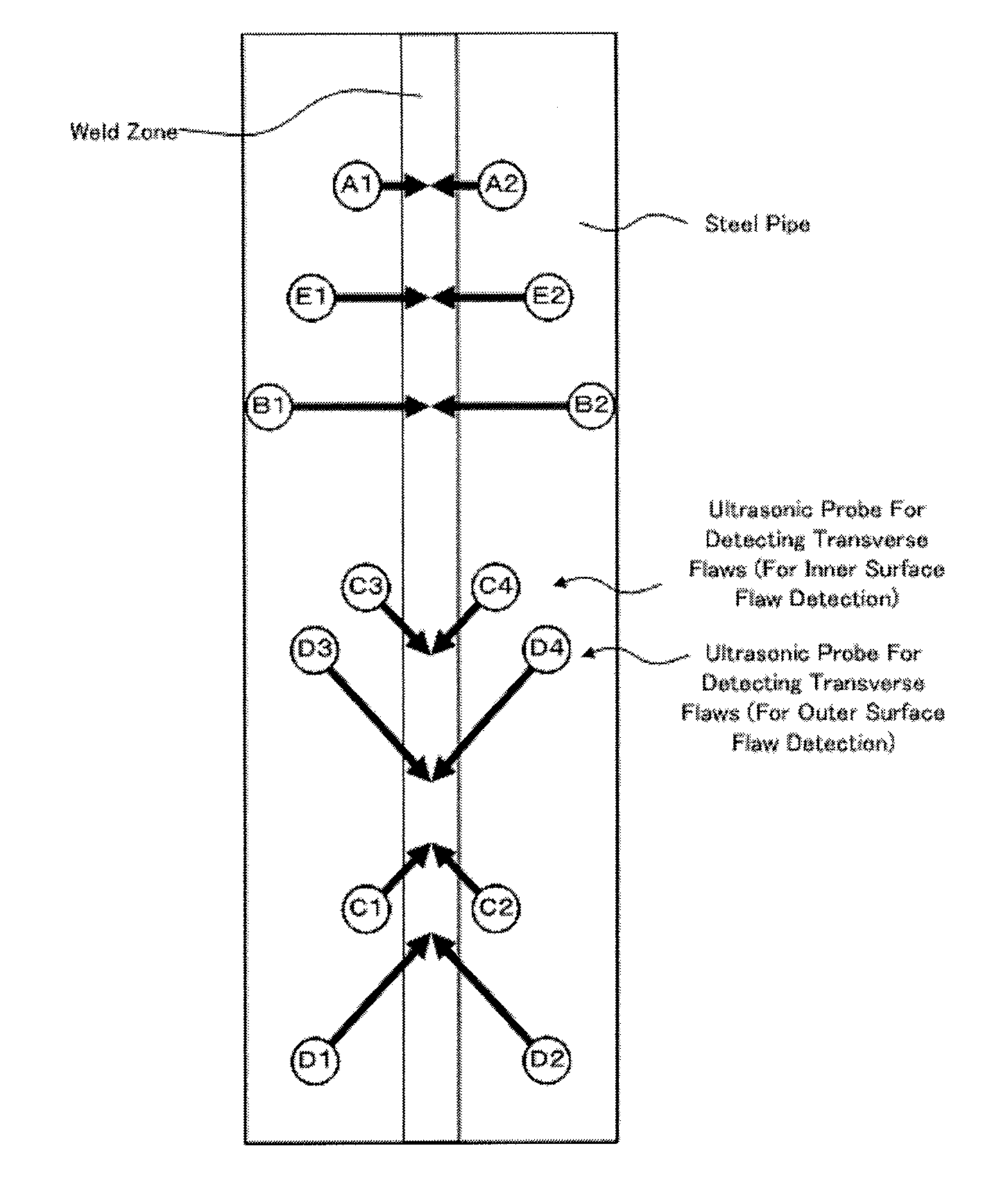
For transverse flaws, however, it is impossible to restrain the effects as described above because the ultrasonic testing of flaws on the inner and outer surfaces can be performed only in specific directions (the transfer direction of the steel pipe or the direction reverse to the transfer direction).
However, an increase in the number of ultrasonic probes to be arranged and the number of flaw detectors connected to each ultrasonic probe results in a steep rise in equipment cost.
In addition, because it is necessary to set the distance between a weld zone and an ultrasonic probe, flaw detection sensitivity and the like for each ultrasonic probe, addition of ultrasonic probes poses a problem of long adjustment time, which is necessary until flaw detection becomes possible.
It is difficult to simultaneously adjust the positions and...

Method used


Image

  • Method and apparatus for ultrasonic testing of weld zones
  • Method and apparatus for ultrasonic testing of weld zones
  • Method and apparatus for ultrasonic testing of weld zones

Examples


Embodiment Construction

[0074]Hereinafter, referring to the accompanying drawings, an embodiment of the present invention will be described by taking the case where the test object is a welded pipe as an example.

[0075]FIG. 5 is a front view showing the rough configuration of an ultrasonic testing apparatus for weld zones in an embodiment of the present invention. FIGS. 6A and 6B are diagrams showing the rough configuration of an ultrasonic probe shown in FIG. 5, FIG. 6A showing a plan view and FIG. 6B showing an enlarged plan view. FIGS. 7A to 7C are diagrams showing the rough configuration of a probe holder to which the ultrasonic probe shown in FIG. 5 is attached, FIG. 7A showing a front view, FIG. 7B showing a back view, and FIG. 7C a side view.

[0076]As shown in FIGS. 5 to 7, an ultrasonic testing apparatus 100 of this embodiment includes an ultrasonic probe 1 and transmission / reception control means 2. The ultrasonic probe 1 is provided with n (n≧2) transducers 11 arranged along a direction orthogonal ...


PUM


Abstract

Provided are an ultrasonic testing method and an ultrasonic testing apparatus capable of accurately detecting flaws present in a weld zone of a test object, such as a welded pipe, regardless of the position of the flaws. An ultrasonic testing apparatus 100 includes an ultrasonic probe 1 which is provided with n (n≧2) transducers 11 arranged along a direction orthogonal to the weld line of a weld zone P1 of a test object P and is arranged so as to face the weld zone, and transmission/reception control means 2 which selects m (n>m≧1) transducers from the n transducers, causes the selected transducers to transmit and receive ultrasonic waves to and from the weld zone, and switches the selected transducers one after another. The transmission/reception control means switches the selected transducers one after another so that the range of an effective beam width of each of the selected transducers that have been switched for a flaw to be detected has an overlapping portion, and in the transmission/reception control means, the flaw detection sensitivity is adjusted beforehand for each of the selected transducers so that maximum echo intensities from a flaw to be detected, which are each received by each of the selected transducers that have been switched, become substantially equal to each other.

Description

TECHNICAL FIELD[0001]The present invention relates to an ultrasonic testing method and an ultrasonic testing apparatus capable of accurately detecting flaws present in a weld zone of a test object, such as a welded pipe or tube, regardless of the positions of the flaws. Hereinafter, “pipe or tube” is referred to as pipe when deemed appropriate.BACKGROUND ART[0002]Depending on welding methods and welding conditions, various flaws occur in a weld zone of a test object, such as a welded pipe. These flaws cause a quality deterioration of the weld zone. For this reason, the nondestructive inspection of weld zones is carried out using X-rays and ultrasonic waves.[0003]X-ray inspection can easily detect spot flaws, such as pinholes and slag inclusions, and has been used in many inspections. However, X-ray inspection has problems of low inspection efficiency, high equipment cost, and the like. For this reason, in submerged arc welded (SAW) steel pipe, ultrasonic testing is first performed a...

Claims


Application Information

Patent Timeline
IPC IPC(8): G01N29/00
CPCG01N29/262G01N2291/2675G01N2291/106G01N29/043G01N29/2487G01N2291/056
Inventor YAMANO, MASAKIOKUBO, HIROYUKIHORIKIRI, TAKUMI
Owner NIPPON STEEL CORP
Why Eureka
Try Eureka