
O-space imaging

a space imaging and satellite technology, applied in the field of satellite imaging methods and systems, can solve the problems of increasing the number of coils and the ratio of acceleration gain to expense of multiple receiver chains, and achieve the effect of reducing the number of coils

Active Publication Date: 2011-10-06
YALE UNIV
View PDF48 Cites 9 Cited by
  • Summary
  • Abstract
  • Description
  • Claims
  • Application Information

AI Technical Summary

Benefits of technology

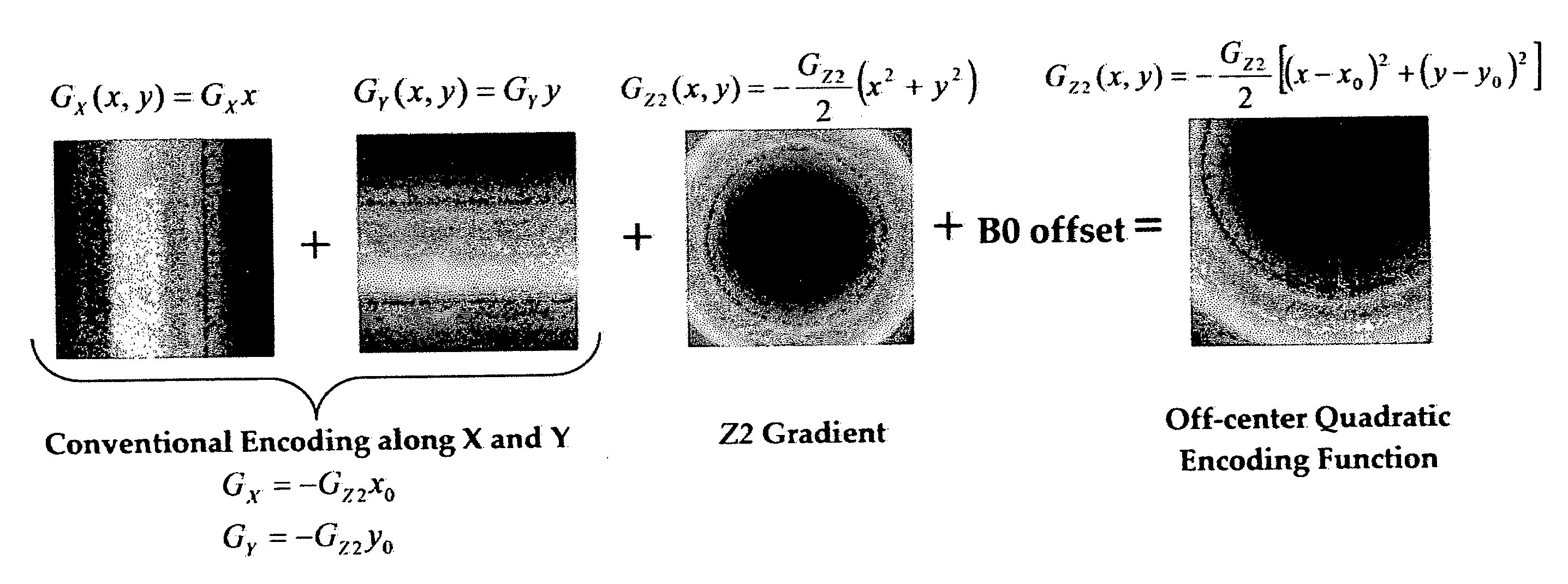
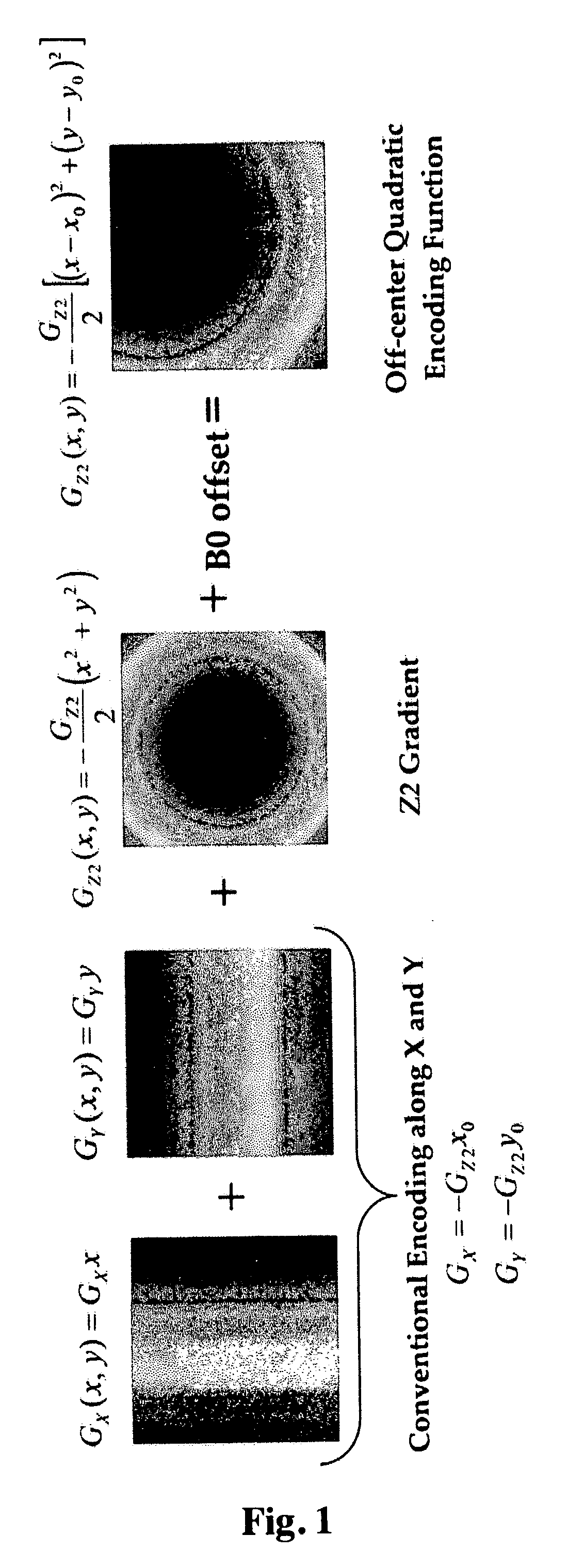
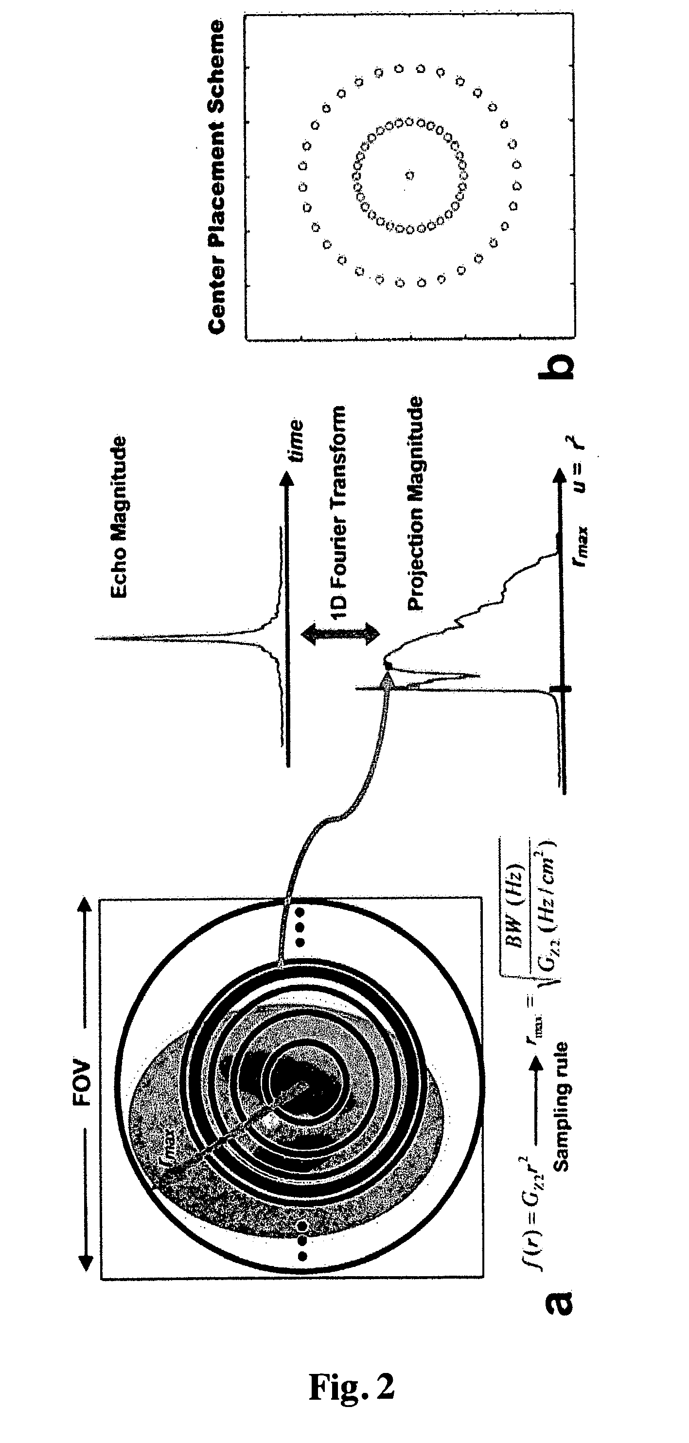
Recent improvements in parallel imaging have been driven by the use of greater numbers of independent surface coils placed so as to minimize aliasing along the phase encode direction. However the gains from increasing the number of coils diminish as coil coupling problems begin to dominate and the ratio of acceleration gain to expense for multiple receiver chains becomes prohibitive. In this invention, we redesigned the spatial encoding strategy used in order to gain efficiency, achieving a gradient encoding scheme that is complementary to the spatial encoding provided by the receiver coils. This approach leads to “O-Space” imaging, wherein the spatial encoding gradient shapes are tailored to an existing surface coil array, making more efficient use of the spatial information contained in the coil profiles. In its simplest form, for each acquired echo the Z2 spherical harmonic is used to project the object onto sets of concentric rings, while the X and Y gradients are used to offset this projection within the imaging plane. This invention is presented, algorithms are introduced for image reconstruction, and the results reveal that O-Space encoding achieves high efficiency compared to Cartesian parallel imaging, suggesting that O-Space imaging holds great potential for highly accelerated scanning.

Problems solved by technology

However the gains from increasing the number of coils diminish as coil coupling problems begin to dominate and the ratio of acceleration gain to expense for multiple receiver chains becomes prohibitive.

Method used


Image

  • O-space imaging
  • O-space imaging
  • O-space imaging

Examples


Embodiment Construction

In the O-Space approach of this invention, parallel imaging performance is optimized using linear combinations of multiple spherical harmonics to form gradient shapes tailored to the spatial information contained in the coil profiles (15). In principle, arbitrary gradient shapes can be chosen for each successive echo to obtain different projections of the object. In its most general form, one begins with an array of surface coil profiles, assesses their spatial encoding ability, and then designs a nonlinear gradient encoding scheme that is maximally complementary to the coil array. In a typical circumferential coil array, the profiles vary smoothly throughout the FOV, but the regions of peak sensitivity are relatively localized in angular regions near each coil. A circumferential array therefore provides more encoding in the angular direction than in the radial direction, a fact that has not been exploited by gradient encoding schemes in the past.

According to an embodiment of the in...


PUM


Abstract

In MRI by excitation of nuclear spins and measurement of RF signals induced by these spins in the presence of spatially-varying encoding magnetic fields, signal localization is performed through recombination of measurements obtained in parallel by each coil in an encircling array of RF receiver coils. Through the use of magnetic gradient fields that vary both as first-order and second-order Z2 spherical harmonics with position, radially-symmetric magnetic encoding fields are created that are complementary to the spatial variation of the encircling receiver coils. The resultant hybrid encoding functions comprised of spatially-varying coil profiles and gradient fields permits unambiguous localization of signal contributed by spins. Using hybrid encoding functions in which the gradient shapes are thusly tailored to the encircling array of coil profiles, images are acquired in less time than is achievable from a conventional acquisition employing only first-order gradient fields with an encircling coil array.

Description

FIELD OF THE INVENTIONThe invention relates generally to parellel imaging methods and systems. In particular, the invention related to methods and systems incorporating highly efficient parallel imaging using second-order nonlinear fields as encoding gradients with no phase encoding.BACKGROUND OF THE INVENTIONParallel imaging methods exploit the spatial encoding contained in independent RF coil profiles to perform image reconstruction from undersampled k-space data (1). Aliasing artifacts are removed using the spatial information of the coil profiles to fill in missing phase encode lines either in the image domain, as in SENSE (2), or in k-space, as in GRAPPA (3). Parallel imaging performance is evaluated based on the geometry factor, or g-factor, which maps the amount of noise amplification that occurs in each voxel as a result of the image reconstruction problem being underdetermined by linear dependence between the coil profiles (2,4). Extensive efforts have been invested into op...

Claims


Application Information

Patent Timeline
IPC IPC(8): G01R33/48
CPCG01R33/3415G01R33/5611G01R33/4824
Inventor CONSTABLE, ROBERT TODDSTOCKMANN, JASONTAM, LICK-KONG
Owner YALE UNIV
Learn More