Method of displaying applications in a multi-monitor computer system and multi-monitor computer system employing the method

a multi-monitor computer system and application technology, applied in computing, instruments, electric digital data processing, etc., can solve the problems of reducing the utilization of software features and providing any immediate visual feedback

Active Publication Date: 2011-10-06
SMART TECH INC (CA)
View PDF0 Cites 48 Cited by
  • Summary
  • Abstract
  • Description
  • Claims
  • Application Information

AI Technical Summary

Benefits of technology

[0012]In accordance with another aspect, there is provided a method of managing applications in a multi-monitor computer system comprising a plurality of display devices, said method comprising: receiving a pointer-down input gesture on an application window; in the event that a threshold condition is satisfied by the input gesture, automatically displaying a dialog box with a plurality of potential destination display devices; receiving the user's selection of a destination display device; and in response to the user's selection, moving the application window entirely into the selected destination display device.
[0013]In accordance with another aspect, there is provided a com

Problems solved by technology

When the physical display devices are closely spaced, although having to manipulate the displayed application windows may be inconvenient, it is a task that can be readily performed by the user.
As will be appreciated, this procedure can be inconvenient especially when the interactive whiteboards are separated by significant distances leading to user frustration and a reduction in the utilization of software features.
Thus, participants first joining a conference are not provided v

Method used


Image

  • Method of displaying applications in a multi-monitor computer system and multi-monitor computer system employing the method
  • Method of displaying applications in a multi-monitor computer system and multi-monitor computer system employing the method
  • Method of displaying applications in a multi-monitor computer system and multi-monitor computer system employing the method

Examples


Embodiment Construction

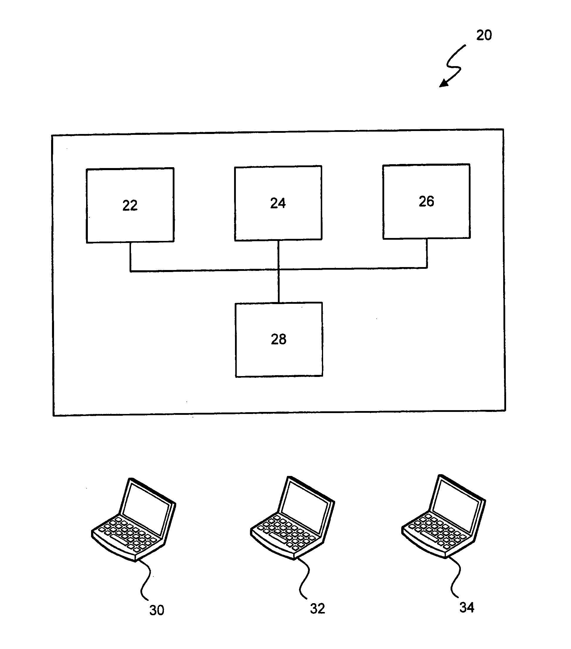
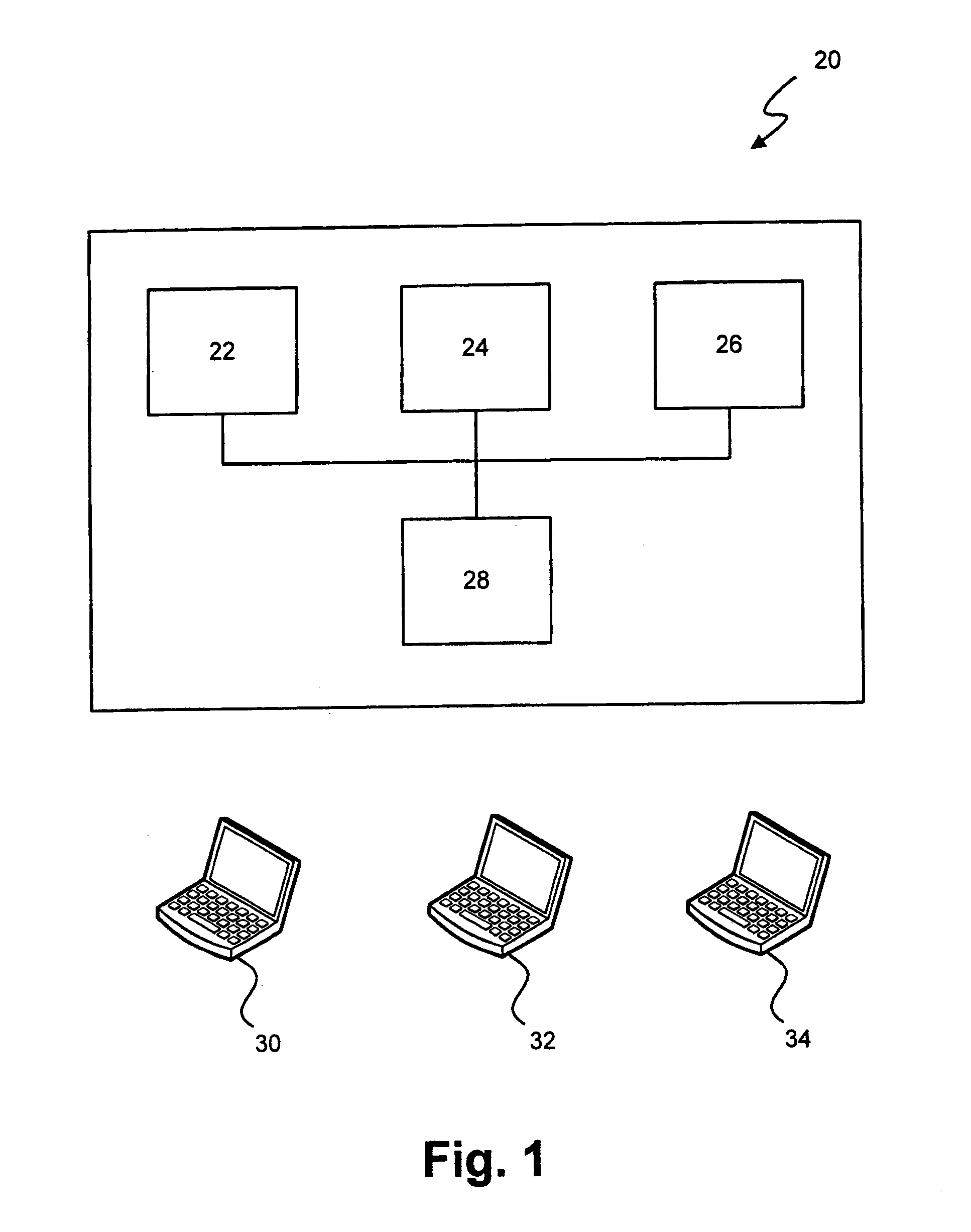
[0031]Turning now to FIG. 1, a multi-monitor computer system is shown and is generally identified by reference numeral 20. As can be seen, in this embodiment the multi-monitor computer system comprises a plurality of physical display devices 22, 24 and 26, each of which is connected to a common computing device, in this case a central computer 28. The physical display devices 22, 24 and 26 may take a variety of forms. For example, the physical display devices may be monitors (i.e. liquid crystal displays (LCDs), cathode ray tubes (CRTs), plasma display devices or other type of display panel) of the same type or of different types and / or may be of the same or different resolution. Alternatively, the physical display devices 22, 24 and 26 may be interactive whiteboards (IWBs). Each IWB may be one of a number of types including but not limited to analog resistive, capacitive, camera-based, electromagnetic, surface acoustic wave etc. Of course, the physical display devices 22, 24 and 26...


PUM


Abstract

A multi-monitor computer system includes a plurality of display devices communicating with at least one computing device executing an application management procedure. The application management procedure enables an application window available on one display device to be moved entirely to another display device by selecting the other display device from a dialog box displayed in response to a pointer-dragging input gesture on the application window.

Description

[0001]This application is a national stage of PCT / CA2009 / 001223, filed on Sep. 3, 2009, which claims priority to U.S. Provisional Patent Application No. 61 / 094,046, filed on Sep. 3, 2008. Each of these documents is incorporated herein by reference in its entirety.FIELD OF THE INVENTION[0002]The present invention relates generally to multi-monitor computer systems and in particular, to a method of displaying applications in a multi-monitor computer system and to a multi-monitor computer system employing the method.BACKGROUND OF THE INVENTION[0003]Multi-monitor computer systems comprising multiple physical display devices connected to a common computing device such as for example a personal computer or the like, in order to provide an increased display area for computer programs running on the computing device, are becoming increasingly more popular. Depending on the environment, the physical display devices may be of different types (i.e. liquid crystal displays (LCDs), cathode ray t...

Claims


Application Information

Patent Timeline
IPC IPC(8): G09G5/00G06F3/033
CPCG06F3/017G06F3/04883G06F3/1415G09G2370/16G06F3/1454G09G2340/0464G09G2370/042G06F3/1423
Inventor HILL, DOUGLAS B.ROUNDING, MICHAELMITCHELL, DANIELMARTIN, DAVIDWANG, LUGINGFORREST, GREGORY
Owner SMART TECH INC (CA)
Why Eureka
Try Eureka