System and method for providing pseudowire group labels in a network environment

a network environment and pseudowire technology, applied in the field of communication, can solve the problems of component manufacturers, system designers, network operators, and inability to quickly and effectively provision connections, and achieve the effect of reducing the number of components and reducing the number of network operators

Inactive Publication Date: 2011-10-06
CISCO TECH INC
View PDF8 Cites 22 Cited by
  • Summary
  • Abstract
  • Description
  • Claims
  • Application Information

AI Technical Summary

Problems solved by technology

In particular, the ability to quickly and to effectively provision connections presents a significant challenge to component manufacturers, system designers, and network operators.
Certain issues have arisen in pseudowire scenarios, where faults are detected in the network.

Method used


Image

  • System and method for providing pseudowire group labels in a network environment
  • System and method for providing pseudowire group labels in a network environment
  • System and method for providing pseudowire group labels in a network environment

Examples


example embodiments

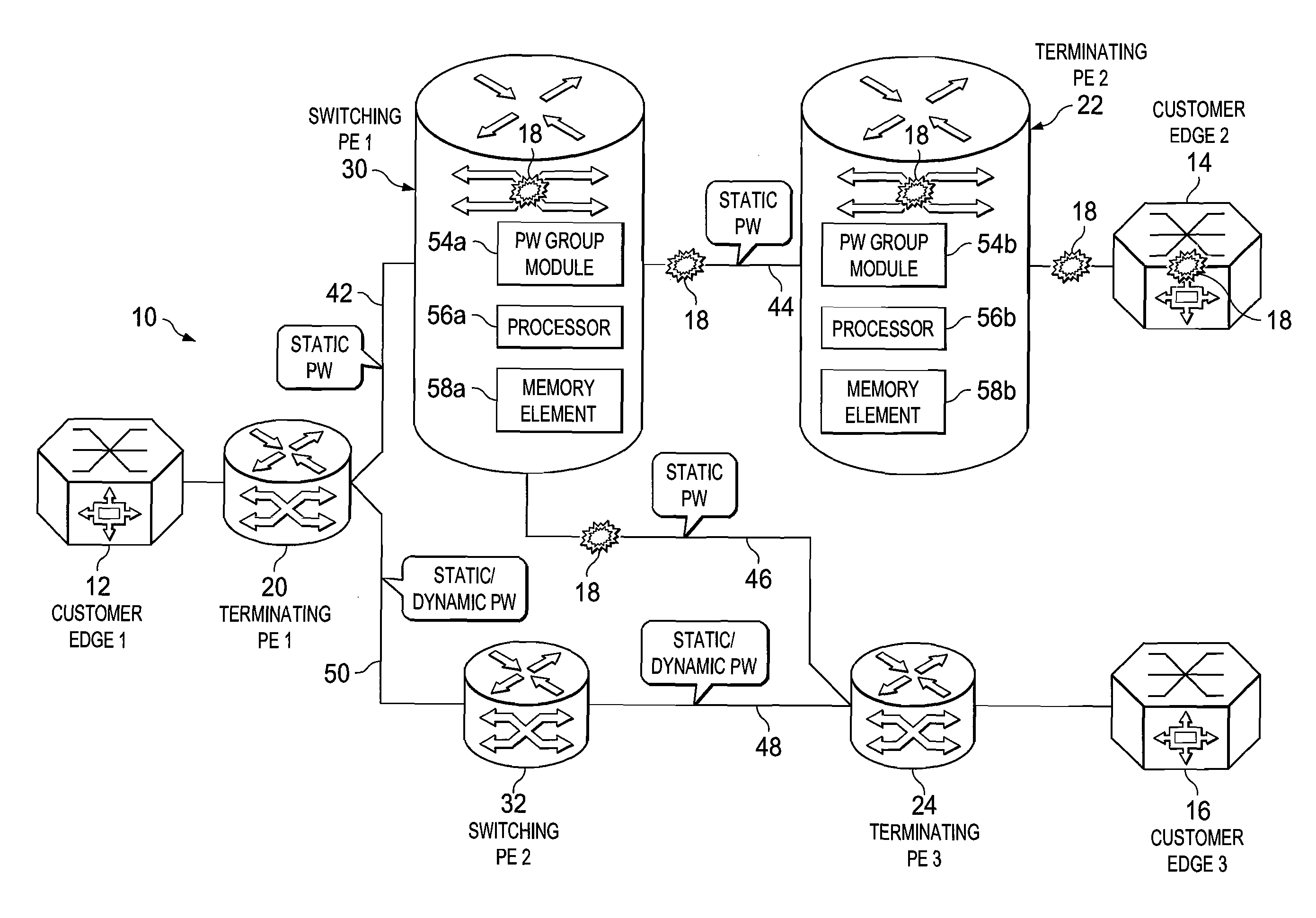
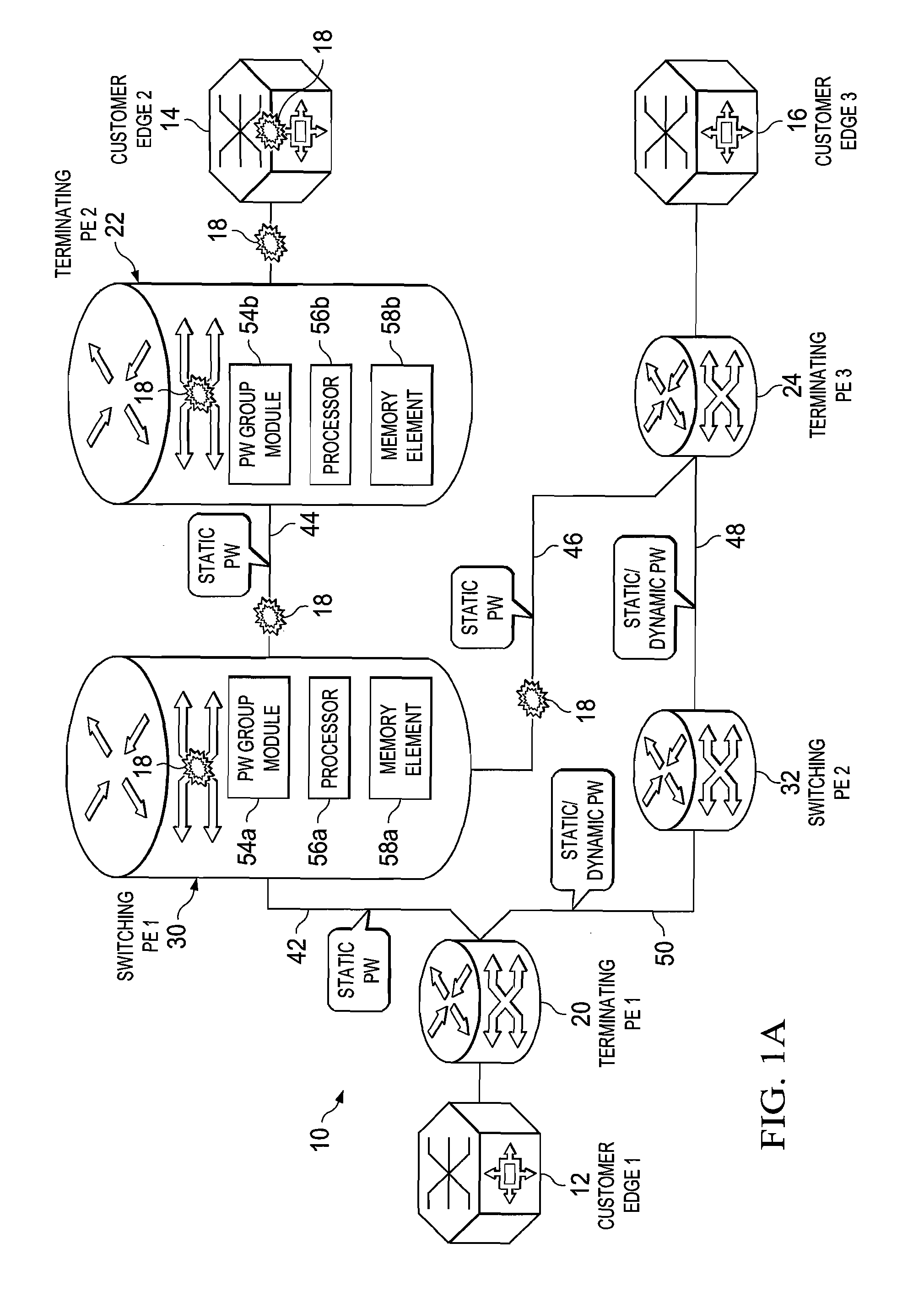
[0012]FIG. 1A is a simplified block diagram of a communication system 10 for providing pseudowire group labels in accordance with one example of the present disclosure. FIG. 1A includes a customer edge 1 (CE1) 12, a CE214, and a CE316, where a number of faults 18 are shown as propagating in the network. Typically, when an error or a failure occurs in the network (e.g., an interface failure, a pulled cable, a switch failure, hardware / software failures generally, etc.), messages are sent to various network devices in order to inform them of these fault conditions. Faults 18 of FIG. 1A are indicative of such messages, where the underlying fault condition (being signaled by the messages) can occur virtually anywhere in a network (e.g., in a customer edge, in provider equipment, etc.). FIG. 1A also includes a terminating provider equipment 1 (TPE1) 20, a TPE222, a TPE324, a switching provider edge 1 (SPE1) 30, and a SPE232. In one particular example implementation, the TPEs and SPEs of F...


PUM


Abstract

An example method includes identifying a fault condition in a network, and evaluating pseudowires affected by the fault condition in order to make a determination as to whether an aggregate failure occurred in the network for a group of pseudowires. The method also includes communicating a group message indicating that the group of pseudowires is associated with the fault condition. The group message includes a group identification (ID), which identifies the group of pseudowires, and the group message includes a pseudowire group label identifying an in-band aggregate channel. More specifically, the pseudowire group label can be applicable to static pseudowires. In more detailed embodiments, the group ID identifies the group of pseudowires that are associated with an attachment circuit, a label switched path, or a port. Internal mappings can be maintained such that a plurality of pseudowires is mapped to individual interfaces of network elements in the network.

Description

TECHNICAL FIELD[0001]This disclosure relates in general to the field of communications and, more particularly, to providing pseudowire group labels in a network environment.BACKGROUND[0002]The field of communications has become increasingly important in today's society. In particular, the ability to quickly and to effectively provision connections presents a significant challenge to component manufacturers, system designers, and network operators. Multiprotocol Label Switching (MPLS) is a mechanism in telecommunications networks that carries data from one network node to the next. Layer 2 services (such as Frame Relay, Asynchronous Transfer Mode, and Ethernet) can be emulated over an MPLS backbone by encapsulating the Layer 2 Protocol Data Units (PDUs) and transmitting them over pseudowires. Protocols exist for establishing and maintaining the pseudowires. Certain issues have arisen in pseudowire scenarios, where faults are detected in the network.BRIEF DESCRIPTION OF THE DRAWINGS[0...

Claims


Application Information

Patent Timeline
Patent Type & Authority Applications(United States)
IPC IPC(8): H04L12/26
CPCH04L43/0817H04L43/10Y02B60/33H04L45/28H04L45/68H04L45/245Y02D30/50
Inventor RUSTOGI, SUDHIR KUMARHUSSAIN, IFTEKHAR
Owner CISCO TECH INC
Why Eureka
Try Eureka