Optoelectrical Connector

a technology of optoelectric connectors and connectors, applied in the field of optoelectric connectors, can solve the problems of short circuit, disadvantageous electrical shock, direct touch of parts, etc., and achieve the effect of high processing accuracy

Active Publication Date: 2011-10-06
JAPAN AVIATION ELECTRONICS IND LTD
View PDF18 Cites 12 Cited by
  • Summary
  • Abstract
  • Description
  • Claims
  • Application Information

AI Technical Summary

Benefits of technology

[0007]The present invention has such structure that the conductive contacts are provided in the opening of the receptacle housing, the conductive cylindrical member to which the wire is assembled is provided in the opening of the plug housing, and the contacts and the cylindrical member contact with each other when the plug is inserted into the receptacle, so that parts serving electrical connection are not exposed. Therefore, electrical shock caused by exposition of the parts serving the electrical connection can be prevented and further, short-circuiting, malfunction, and the like caused by attachment of a foreign material and the like can be prevented advantageously. Further, the ferrule and the sleeve are insulators, so that when a ceramic member such as zirconia, for example, is used as a constituent element, abrasion accompanied by use can be prevented and high processing accuracy can be maintained.

Problems solved by technology

In the configuration disclosed in Patent literature 1, parts which serve electrical connection (the wire springs 710 of the receptacle 700 and the metallic blades 810 of the plug 800) are exposed, so that a person can directly touch the parts and may get an electrical shock disadvantageously.
Further, since the parts which serve electrical connection are exposed, a hand or foreign materials may contact to the parts and therefore scurf, foreign materials, and the like are attached to the parts to cause performance degradation, short-circuiting, and malfunctions.
However, the problem is not fundamentally solved and the configuration of Patent literature 2 still has a similar problem to that of Patent literature 1.
This abrasion and degradation of processing accuracy cause displacement of central positions of the two optical fibers 5 and 6 that perform optical connection, causing performance degradation and the like.

Method used


Image

  • Optoelectrical Connector
  • Optoelectrical Connector
  • Optoelectrical Connector

Examples


Embodiment Construction

[0028]Embodiments of the present invention will be described below with reference to the accompanying drawings.

[0029]300>

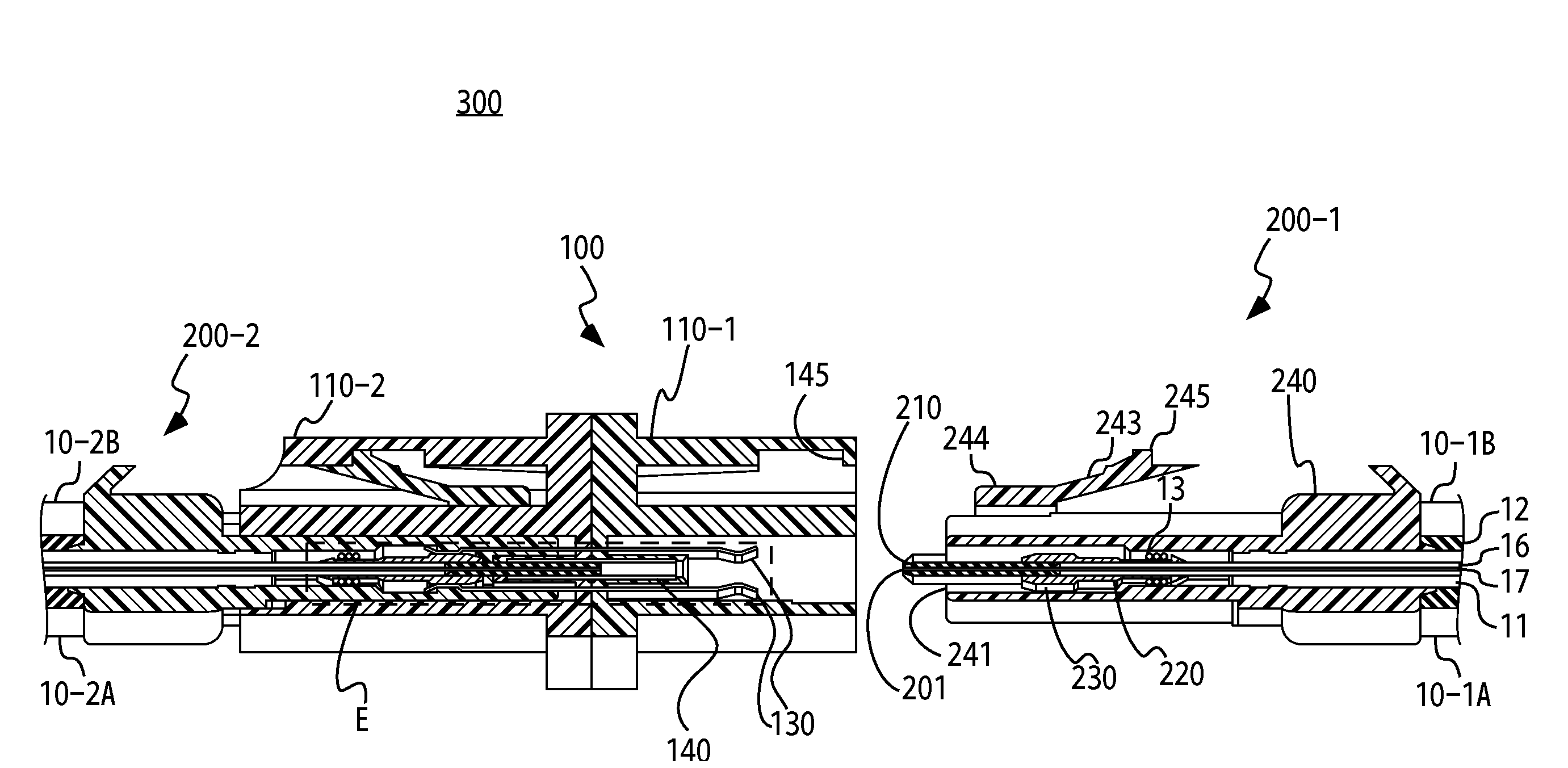
[0030]An optoelectrical connector 300 according to an embodiment is described. The optoelectrical connector 300 includes a receptacle 100 and plugs 200-1 and 200-2, and connects wires and optical fibers of photoelectric composite cables 10-1A and 10-1B with wires and optical fibers of other photoelectric composite cables 10-2A and 10-2B respectively.

[0031]FIGS. 4 to 6 are sectional views of the optoelectrical connector 300. The configuration of the receptacle 100 is first described with reference to FIGS. 4, 7 to 9, and 13, and the configuration of the plug 200-1 is described with reference to FIGS. 4, 10, 11, and 13. FIGS. 4 to 6 illustrate an axial-direction section which is taken along an X-X′ line of FIGS. 8 and 11 and viewed from a direction of an arrow A shown in FIGS. 7, 8, 10, and 11. FIG. 12 is a sectional view of the photoelectric composite cable 10 (10-...


PUM


Abstract

An optoelectrical connector is composed of a plug to which a wire and an optical fiber are assembled and a receptacle to which the plug is inserted and connected. A receptacle includes insulation sleeves and conductive contacts in openings of receptacle housings, and plugs include a ferrule assembled bodies which are composed of an insulation ferrule which holds an optical fiber and a conductive cylindrical member which holds the ferrule and to which a wire is assembled, in an opening of the plug housing. When the plugs are inserted into the receptacle, the contacts and the cylindrical member contact with each other and the ferrules are inserted into the sleeves. Parts which serve electrical connection are not exposed.

Description

TECHNICAL FIELD[0001]The present invention relates to an optoelectrical connector that is composed of a plug to which an electrical wire and an optical fiber are assembled and a receptacle to which the plug is inserted and connected.BACKGROUND ART[0002]Japanese Patent Application Laid Open No. 2002-182070 (published on Jun. 26, 2002, and referred to below as Patent literature 1) discloses an optoelectrical connector that is used at a terminal of a photoelectric transmission medium and has an optical connector shape. FIGS. 1 and 2 respectively illustrate the configuration of a receptacle and the configuration of a plug that are described in Patent literature 1. As shown in FIG. 1, a receptacle 700 includes conductive wire springs 710 at an end part thereof. As shown in FIG. 2, a plug 800 includes metallic blades 810 corresponding to the wire springs 710 of the receptacle 700, at a lower surface thereof. Electrical connection is performed when the wire springs 710 and the metallic bla...

Claims


Application Information

Patent Timeline
Patent Type & Authority Applications(United States)
IPC IPC(8): G02B6/36
CPCG02B6/3817G02B6/4246G02B6/3825
Inventor KOREEDA, YUICHIHASHIGUCHI, OSAMU
Owner JAPAN AVIATION ELECTRONICS IND LTD
Why Eureka
Try Eureka