Methods, systems and apparatus relating to tip clearance calculations in turbine engines

Active Publication Date: 2011-10-06
GENERAL ELECTRIC CO
View PDF7 Cites 24 Cited by
  • Summary
  • Abstract
  • Description
  • Claims
  • Application Information

AI Technical Summary

Benefits of technology

[0008]In one or more combustion turbine engines that each include an inner turbine shell and an outer turbine shell, and a row of rotor blades that includes at least one rotor blade having blade tips and surrounding stationary structure that surrounds the row of rotor blades at a position just outboard of the blade tips such that a tip clearance is defined between the blade tips and the surrounding stationary structure, the present application further describes another method of calculating the tip clearance during operation of the combustion turbine engine. This method may include the following steps: positioning a first proximity sensor within the hot-gas path of a first combustion turbine engine in a predetermined location so that the first proximity sensor measures the tip clearance; positioning a second proximity sensor in a predetermined location outside of the hot-gas path of the first combustion turbine engine so that the seco

Problems solved by technology

During operation, because of the extreme temperatures of the hot-gas path, the velocity of the working fluid, and the rotational velocity of the engine, rotor blades become highly stressed with extreme mechanical and thermal loads.
Tighter tip clearances, though, increase the risk that rotating parts will make contact with or rub against non-rotating parts during one of the engine's several operational modes, particularly considering the fact that tip clearances generally vary based upon operating conditions.
Of course, having rotating and stationary parts rub or make contact during operation is highly undesirable because it can cause extensive damage to the engine or failure of certain components.
In addition, rubbing may result in increased clearances once the event that caused

Method used


Image

  • Methods, systems and apparatus relating to tip clearance calculations in turbine engines
  • Methods, systems and apparatus relating to tip clearance calculations in turbine engines
  • Methods, systems and apparatus relating to tip clearance calculations in turbine engines

Examples


Embodiment Construction

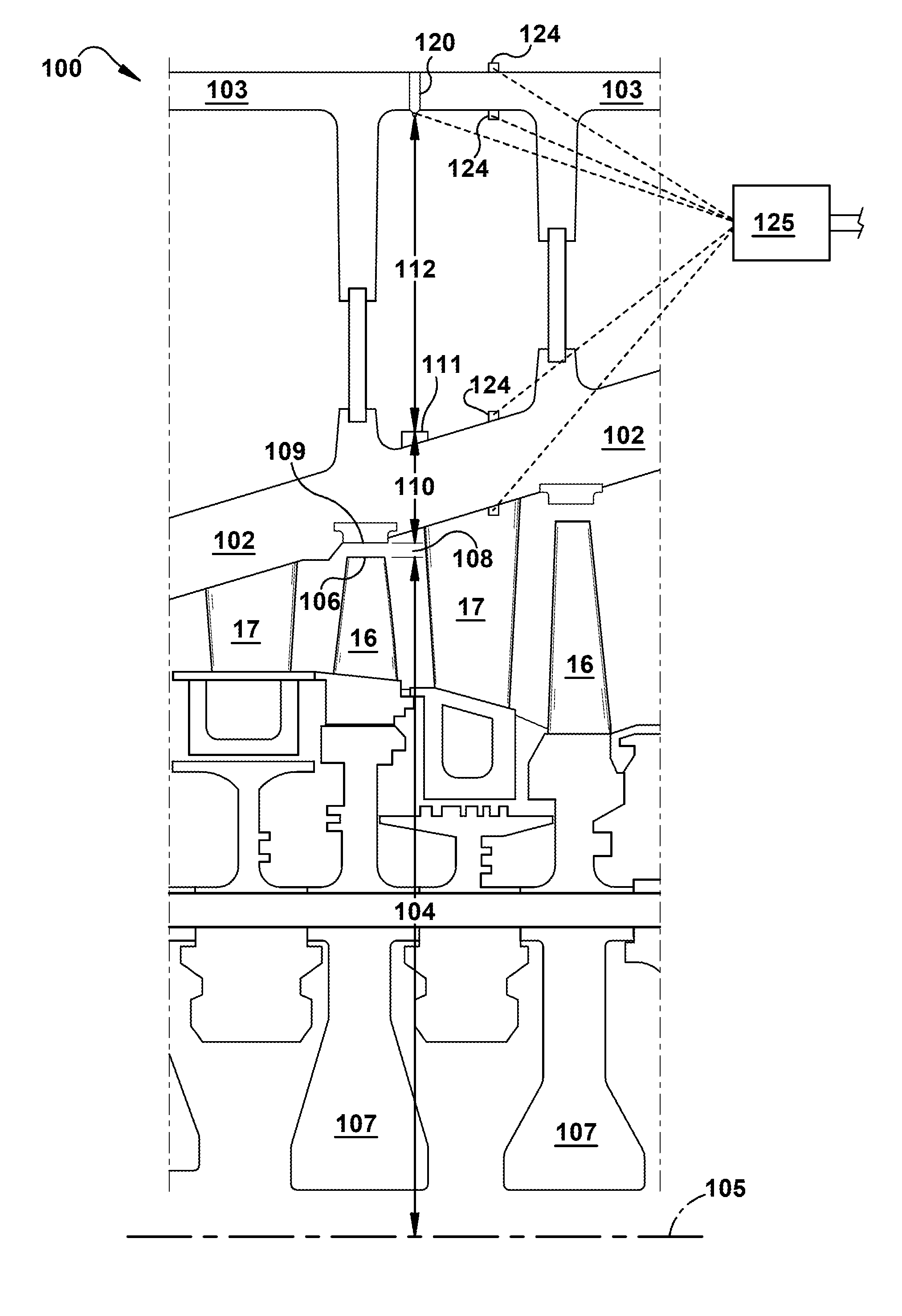
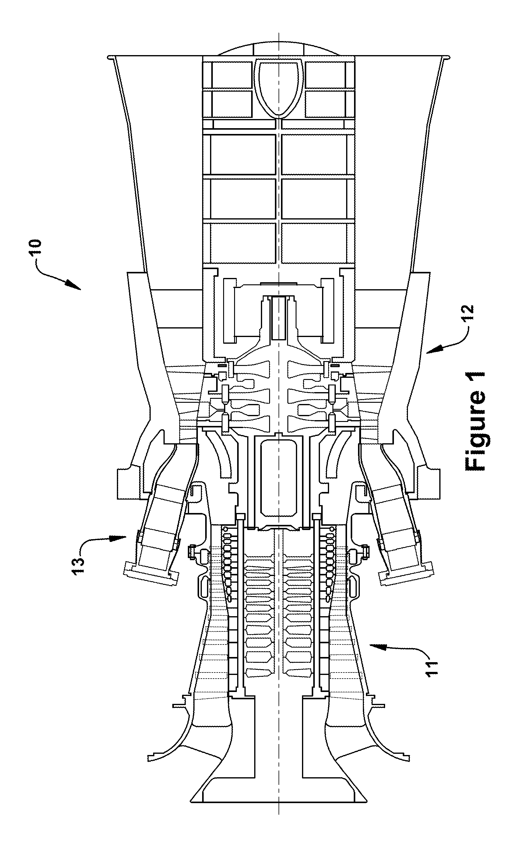
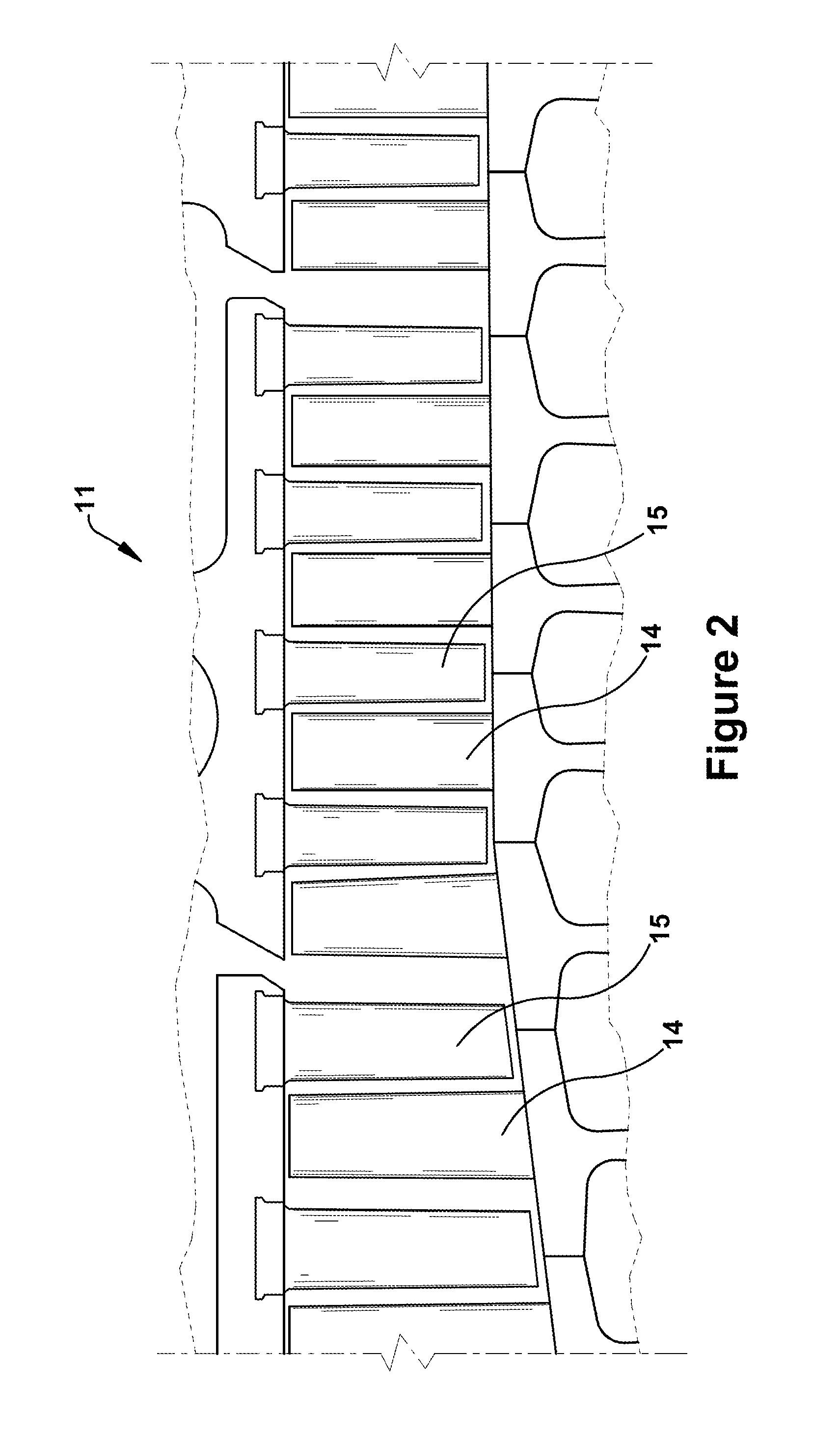
[0019]As an initial matter, to communicate clearly the invention of the current application, it may be necessary to select terminology that refers to and describes certain parts or machine components of a turbine engine and related systems. Whenever possible, industry terminology will be used and employed in a manner consistent with its accepted meaning. However, it is meant that any such terminology be given a broad meaning and not narrowly construed such that the meaning intended herein and the scope of the appended claims is unreasonably restricted. Those of ordinary skill in the art will appreciate that often a particular component may be referred to using several different terms. In addition, what may be described herein as a single part may include and be referenced in another context as consisting of several component parts, or, what may be described herein as including multiple component parts may be fashioned into and, in some cases, referred to as a single part. As such, i...


PUM


Abstract

A method of calculating the tip clearance during operation of a combustion turbine engine that includes the steps of: measuring a cold tip clearance and a cold shell-to-shell distance; while the combustion turbine engine is operating, measuring an operating parameter and measuring a shell-to-shell distance with a proximity sensor; calculating the tip clearance based on the cold tip clearance measurement and the operating parameter measurement; calculating the shell-to-shell distance based on the cold shell-to-shell distance measurement and the operating parameter measurement; comparing the shell-to-shell distance measurement of the proximity sensor with the shell-to-shell distance calculation; and calibrating the calculated tip clearance calculation based on the comparison.

Description

BACKGROUND OF THE INVENTION[0001]This present application relates generally to methods, systems, and apparatus for clearance between a stationary component and a movable component of a rotating machine. More specifically, but not by way of limitation, the present application relates to methods, systems, and apparatus pertaining to measuring blade tip clearance between rotating turbine blades and surrounding stationary structures in combustion turbine engines, which, as used herein and unless specifically stated otherwise, is meant to include all types of turbine or rotary engines, including gas turbine engines, aircraft engines, steam turbine engines.[0002]A gas turbine engine (which, as discussed below, may be used to illustrate an exemplary application of the current invention) includes a compressor, a combustor, and a turbine. The compressor and turbine generally include rows of blades that are axially stacked in stages. Each stage includes a row of circumferentially-spaced stato...

Claims


Application Information

Patent Timeline
IPC IPC(8): F02C7/00G06F19/00
CPCF01D11/20F01D17/02F01D21/003G01B7/06G01B7/12G01B15/00G01B7/14G01B11/06G01B11/08G01B11/12G01B11/14G01B7/13
Inventor HAFNER, MATTHEW TROY
Owner GENERAL ELECTRIC CO
Why Eureka
Try Eureka