
System and Method for Providing Perceived First-Order Control of an Unmanned Vehicle

a technology of perception and control, applied in the field of unmanned vehicle control, can solve the problems of difficult environments, little advance knowledge or information about their surroundings, and often outdated maps,

Inactive Publication Date: 2011-10-06
MASSACHUSETTS INST OF TECH
View PDF7 Cites 60 Cited by
  • Summary
  • Abstract
  • Description
  • Claims
  • Application Information

AI Technical Summary

Benefits of technology

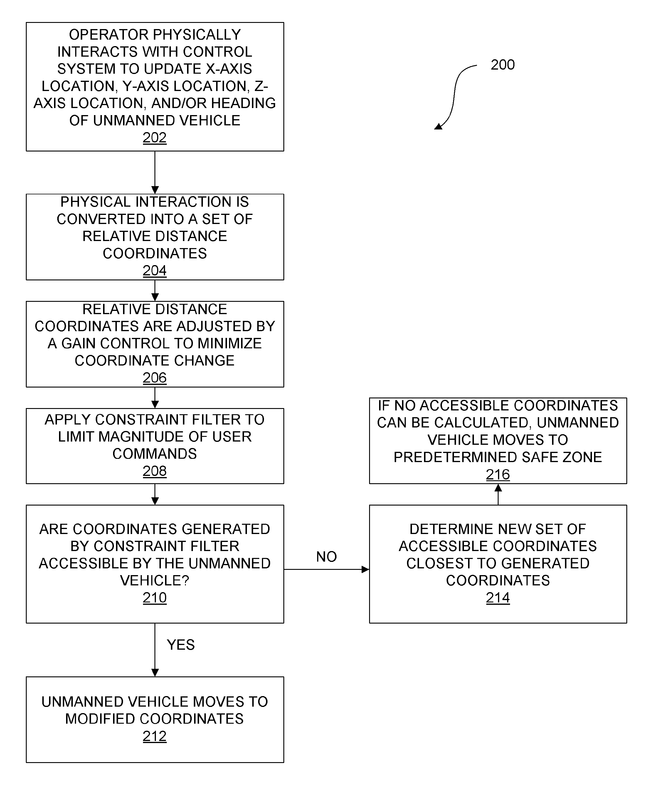
[0015]A screen of the system illustrates an outer circle and a location dot. The outer circle provides a visual illustration of the absolute constraints on movement of the unmanned vehicle. In addition, the location dot provides a visual illustration of the current location of the unmanned vehicle and the degrees of freedom that the user can move the unmanned vehicle. Physical movement of the system results in movement of the location dot toward or away from the outer circle, thereby allowing the operator of the system to control the rate of position update data, and providing the operator with a sense of position and velocity of the unmanned vehicle.

Problems solved by technology

Field personnel, such as soldiers, police SWAT teams, and first responders face challenging, dangerous environments, often with little advance knowledge or information about their surroundings.
These maps are often outdated, and, due to shadows and shading, give false impressions of elevations and details of the environment.
Combined, these flaws often provide field personnel with a false mental model of their environment.
Unfortunately, existing interfaces for MAVs, and unmanned vehicles in general, ignore the competing needs of field operators, requiring bulky equipment and the full attention of an operator.
These systems require extensive training before an operator can safely and effectively operate the MAV.
This complex feedback loop demands full attention of the operator, and thereby decreases overall SA of the operator of the environment and task at hand.
Due to the increased complexity of the feedback loops and number of actions required to successfully complete a maneuver, the cognitive workload of an operator is significantly higher for 2nd order systems than when operating 0th or 1st order controls, leading to lower performance.
Teleoperation, defined as the remote control of an unmanned vehicle via some set of external controls and displays, only exacerbates these problems because additional communication latencies are introduced into the system, in addition to the lack of sensory perception on the part of the operator, who is not physically present.
When a human actor acts based on a GCS view that is delayed due to system latency, the result is often accidents involving the UAV.
While human operators are thought to be effective 1st order controllers, it is doubtful whether UAV operators can effectively execute 2nd order control of UAVs.
System communication delays, the lack of critical perceptual cues, and the need for extensive training, which can result in pilot-induced oscillations and inappropriate control responses, suggest that 1st order control is a poor approach to any type of UAV (and unmanned vehicle) control.
This problem is likely more serious for MAV operators who are not, by the nature of their field presence, able to devote the necessary cognitive resources needed to fully attend to the control dynamics of the MAV.
By comparison, a 0th order control loop significantly reduces the workload because the operator does not need to continually monitor the movement of the vehicle, such as, but not limited to, as the vehicle turns to a new heading, however, there is some cost in vehicle maneuverability.

Method used


Image

  • System and Method for Providing Perceived First-Order Control of an Unmanned Vehicle
  • System and Method for Providing Perceived First-Order Control of an Unmanned Vehicle
  • System and Method for Providing Perceived First-Order Control of an Unmanned Vehicle

Examples


Embodiment Construction

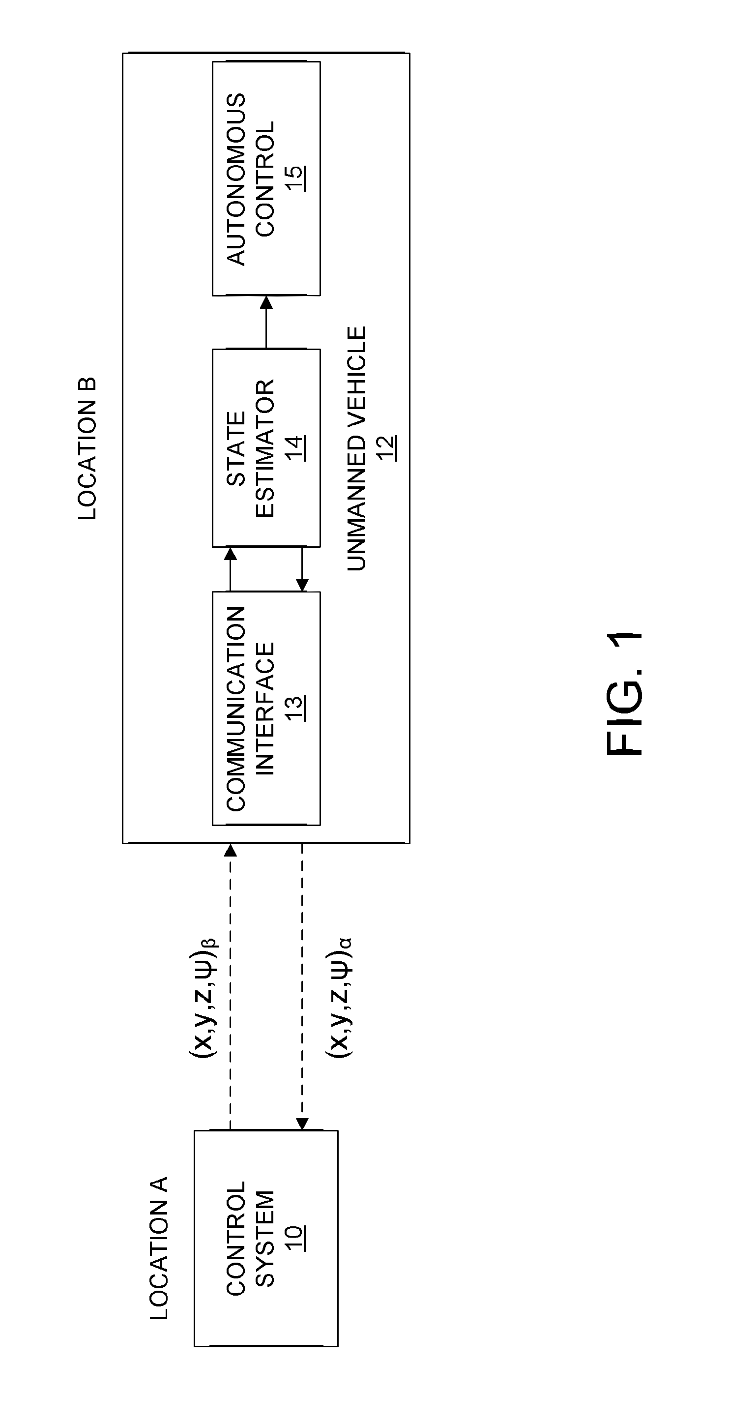
[0026]The present system and method may use multimodal interaction, which uses two or more distinct mediums of interactions to enhance the usability of an interface. Alternatively, a single mode of interaction may be used to interact with the interface. Specifically, the present system and method provides for fine-tune control of unmanned vehicles through use of an interface that provides supervisory control. A perceived first order control is provided by the present system and method, which provides a stable and safe 0th order system control, while allowing operators to perceive 1st order control so as to achieve effective control of an unmanned vehicle with minimal training. An example of such an unmanned vehicle may be, but is not limited to, a Micro Aerial Vehicle (MAV), which is a class of Unmanned Aerial Vehicle (UAV). It should be noted that, although portions of the following description are provided with reference to control of an Unmanned Aerial Vehicle (UAV), the present ...


PUM


Abstract

A system for providing perceived first order control of an unmanned vehicle contains a memory and a processor configured by the memory to perform the steps of receiving instructions for updating x-axis location, y-axis location, z-axis location, and / or heading of the unmanned vehicle; converting received instructions for updating x-axis location, y-axis location, z-axis location, and / or heading of the unmanned vehicle into a set of relative distance coordinates from a current location of the unmanned vehicle; and adjusting the set of relative distance coordinates by a gain control, to minimize coordinate change, wherein gain control provides a rate change in the x-axis location, y-axis location, z-axis location, and / or heading, resulting in a new set of coordinates. A screen displays a location dot representing current location of the unmanned vehicle and an outer limit circle surrounding the location dot representing an outer boundary for movement of the unmanned vehicle.

Description

FIELD OF THE INVENTION[0001]The present invention is generally related to unmanned vehicle control, and more particularly is related to providing perceived first-order control of an unmanned vehicle.BACKGROUND OF THE INVENTION[0002]Field personnel, such as soldiers, police SWAT teams, and first responders face challenging, dangerous environments, often with little advance knowledge or information about their surroundings. Currently, this Intelligence, Surveillance & Reconnaissance (ISR) information is provided by archival pictures, satellite imagery and prior or second-hand experiences. Although satellite imagery is currently the preferred method for gaining Situational Awareness (SA) in military outdoor environments, it has many shortcomings. As is known by those skilled in the art, situational awareness is defined as the combination of perception of elements in the environment, the comprehension of their meaning, and the projection of their status in the future. Operator situation...

Claims


Application Information

Patent Timeline
Patent Type & Authority Applications(United States)
IPC IPC(8): G05D1/00G01C21/00G06F3/01
CPCG06F3/04815G06F3/04883G06F3/04847G05D1/0016
Inventor CUMMINGS, MARY LOUISEPITMAN, DAVID JOSEPHQUIMBY, PAUL WESTLAKE
Owner MASSACHUSETTS INST OF TECH
Learn More