Illumination device, lamp, lighting circuit, and illumination apparatus

a technology of illumination device and lamp, which is applied in the direction of electric variable regulation, process and machine control, instruments, etc., can solve the problems of increasing cost, increasing the difficulty of determining whether the lamp has been replaced, and detecting the end of the life of the lamp, so as to achieve the effect of reliably resetting the cumulative lighting time of the lamp when the lamp is replaced

Inactive Publication Date: 2011-10-13
PANASONIC INTELLECTUAL PROPERTY MANAGEMENT CO LTD
View PDF13 Cites 18 Cited by
  • Summary
  • Abstract
  • Description
  • Claims
  • Application Information

AI Technical Summary

Benefits of technology

[0018]In accordance with the present invention, it is possible to reliabl

Problems solved by technology

However, the illumination device described in JP2001-015276A1 requires a complicated control method for determining a replacement of a lamp in order to reliably restore the dimming ratio to an initial value when the lamp is replaced, which causes an increase in cost.
In contrast, when one or more light emitting elements, such as one or more LEDs, are used as the lamp, it is difficult to detect the end of the life span of th

Method used


Image

  • Illumination device, lamp, lighting circuit, and illumination apparatus
  • Illumination device, lamp, lighting circuit, and illumination apparatus
  • Illumination device, lamp, lighting circuit, and illumination apparatus

Examples


first embodiment

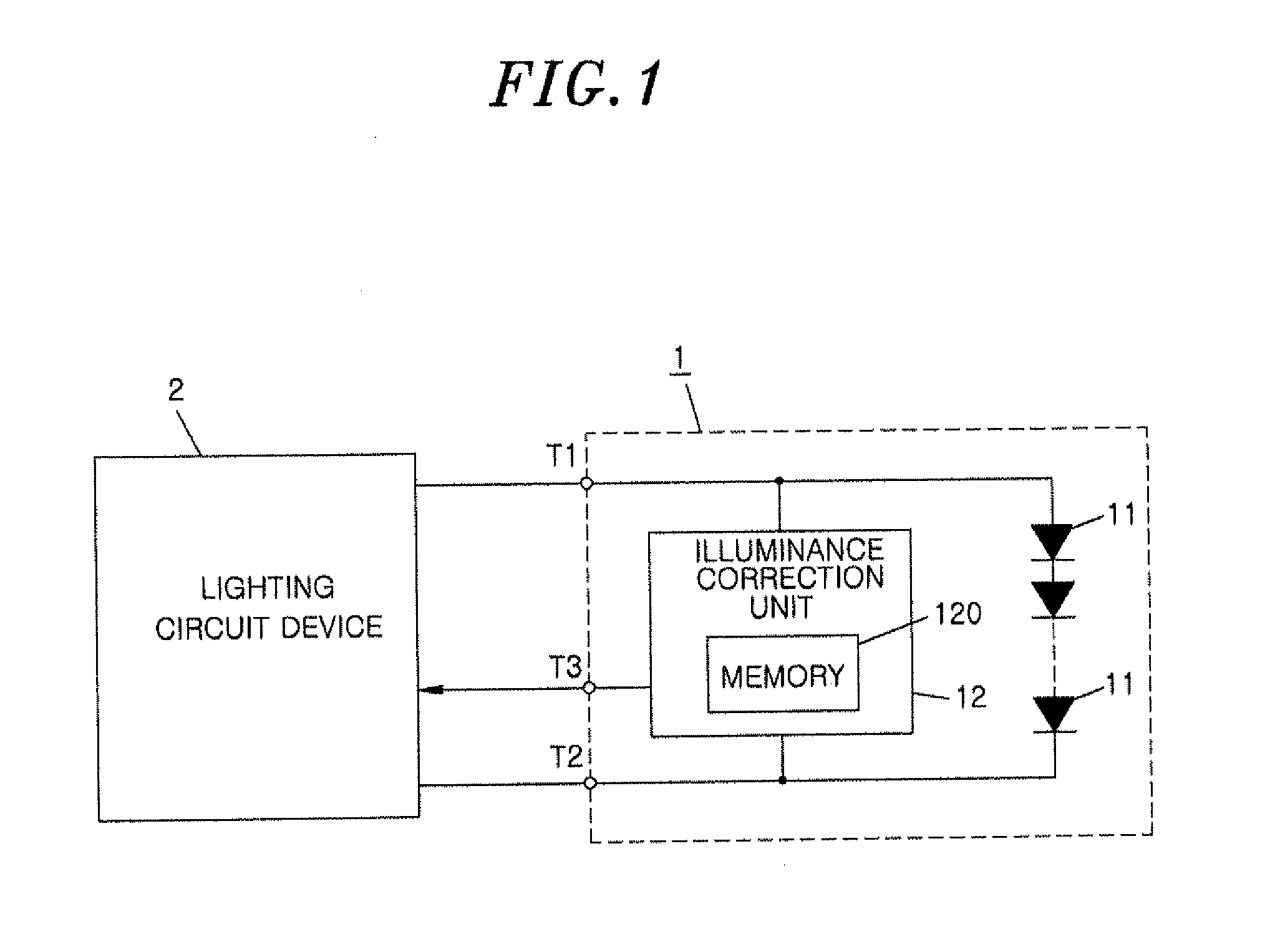
[0033]An illumination device in accordance with a first embodiment of the present invention includes a lamp 1 and a lighting circuit 2, as illustrated in FIG. 1. The lamp 1 is configured to be replaceable and includes one or more light emitting elements 11.

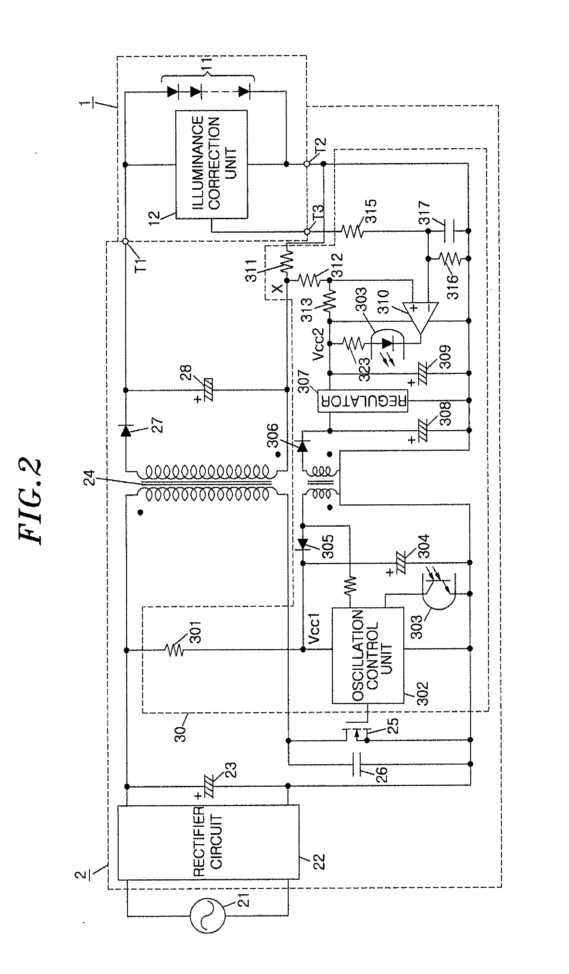
[0034]The lighting circuit 2 includes a lighting device including a flyback DC-DC converter, and causes the lamp 1 to be lit by supplying a power to the light emitting elements11 provided inside the lamp 1 as well as the lighting device. The lamp 1 further includes an illuminance correction unit 12 having a memory 120, in addition to the light emitting elements 11, which will be described in detail later. Here, the term “light emitting element” refers to an element which receives a power and then emits light, such as a Light-Emitting Diode (LED) or an organic Electroluminescent (EL) device. In the present embodiment, LEDs are used as the light emitting elements 11.

[0035]The lighting circuit 2, as shown in FIG. 2, includes a rectif...

second embodiment

[0081]An illumination device in accordance with a second embodiment is different from the illumination device of the first embodiment in that a step-down chopper type converter (step-down chopper circuit) is used in the lighting device of a lighting circuit 2, as shown in FIG. 10. Accordingly, descriptions of the configurations and functions of the present embodiment identical to those of the first embodiment will be omitted here, and only descriptions of the configurations and functions of the present embodiment different from those of the first embodiment will be given below.

[0082]In the step-down chopper circuit, the series circuit of a switch element 31 and a diode 32 are connected in parallel to a smoothing capacitor 23, the switch element 31 being formed of a MOSFET. In the present embodiment, the cathode of the diode 32 is connected to a positive electrode of the smoothing capacitor 23 via the switch element 31. The series circuit of a choke coil 33 and a capacitor 34 are con...

third embodiment

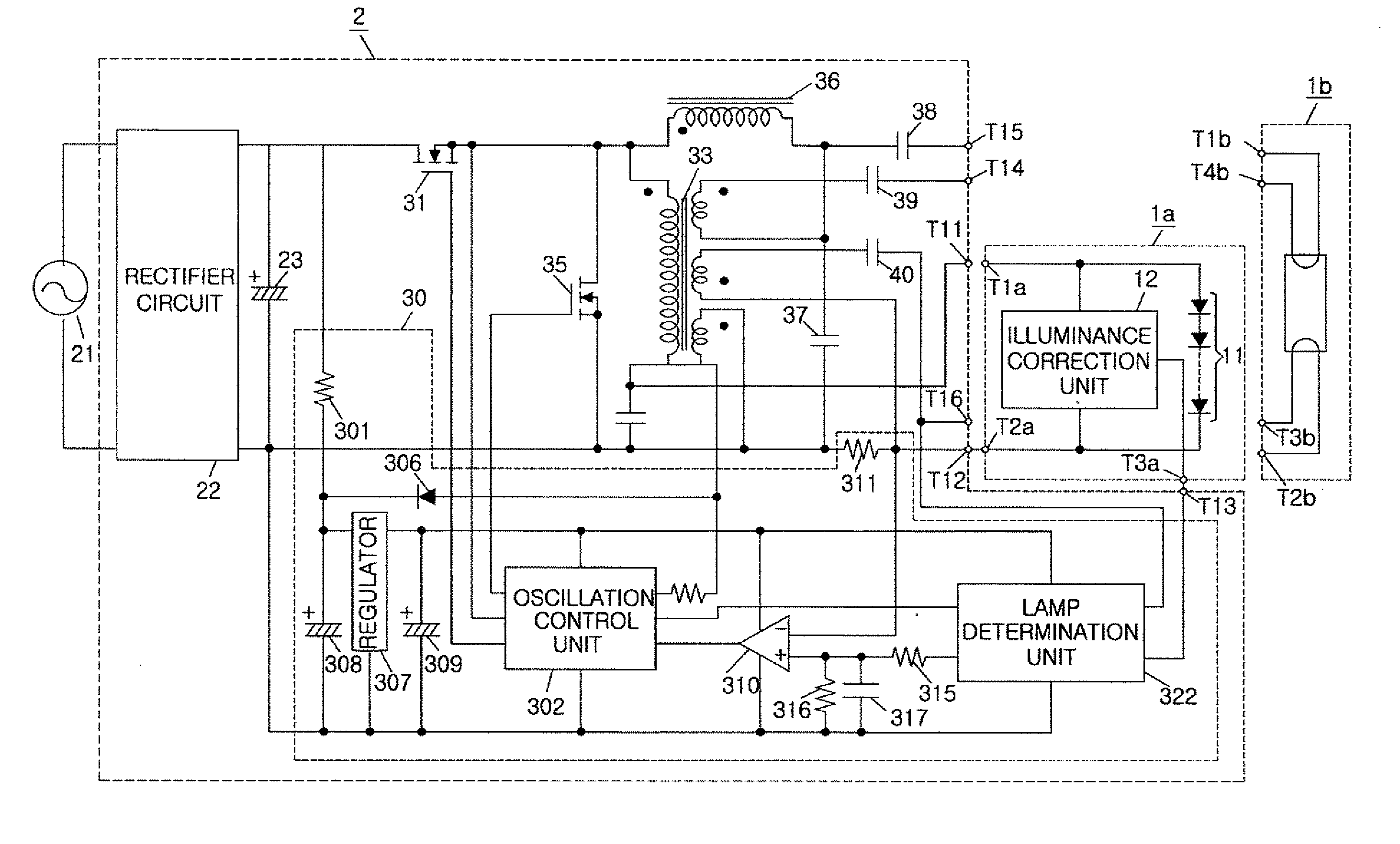
[0098]The illumination device of a third embodiment is different from the illumination device of the second embodiment in that a second lamp 1b including a common fluorescent lamp, as well as a first lamp 1a including light emitting elements (for example, LEDs) 11, can be used together as lamps, as shown in FIG. 12. In the present embodiment, the lamp 1b is formed of a straight, tubular fluorescent lamp, and the lamps 1a and 1b share a common outer appearance.

[0099]A basic configuration is common both to the lighting circuit 2 of the present embodiment and the lighting circuit of FIG. 11 described in conjunction with the second embodiment. In the present embodiment, the lighting circuit 2 includes a second switch element 35, formed of a MOSFET, instead of the diode 32 shown in FIG. 11. When the lighting device is operated as a step-down chopper circuit, a parasitic diode (not shown) embedded in the switch element 35 is used as a diode for the step-down chopper circuit by fixing the ...


PUM


Abstract

An illumination device includes a replaceable lamp including at least one light emitting element; a lighting device for lighting the light emitting element by supplying a power to the lamp; and an illuminance correction unit for performing a dimming control on the lamp. The illuminance correction unit includes a timer for counting a cumulative lighting time of the light emitting element and a memory for storing the cumulative lighting time counted by the timer. The illuminance correction unit determines a dimming ratio of the light emitting element based on the cumulative lighting time stored in the memory and an illuminance correction characteristic, in which the relationship between the cumulative lighting time and the dimming ratio of the light emitting element is determined to uniformly maintain a light output from the light emitting element even when the cumulative lighting time increases. The memory is provided in the lamp.

Description

FIELD OF THE INVENTION[0001]The present invention relates to an illumination device, a lamp, a lighting circuit, and an illumination apparatus that are capable of maintaining the light output from a lamp uniformly in spite of the cumulative lighting time being increased.BACKGROUND OF THE INVENTION[0002]In order to compensate for a reduction in light output resulting from aging of a fluorescent lamp or contamination attributable to long-term use, there has been disclosed an illumination device configured to cumulatively count a lighting time after a replacement of a fluorescent lamp and perform a dimming control so that the dimming ratio can increase in proportion to an increase in the cumulative lighting time. This type of illumination device can prevent the light output from being reduced by aging degradation by, for example, setting an initial value of the dimming ratio to 70% of a rating and gradually increasing the dimming ratio as the cumulative lighting time increases, thereby...

Claims


Application Information

Patent Timeline
IPC IPC(8): H05B37/02H05B37/00H05B44/00
CPCH05B33/0854H05B33/0815H05B45/58H05B47/20H05B45/18H05B45/385H05B45/375
Inventor MITSUYASU, KEIHAMAMOTO, KATUNOBU
Owner PANASONIC INTELLECTUAL PROPERTY MANAGEMENT CO LTD
Why Eureka
Try Eureka