Power System Implantable in Eye

a power system and eye technology, applied in the field of power systems, can solve the problems of permanent damage of optic nerve and retina, increased iop, progressive,

Inactive Publication Date: 2011-10-13
ALCON RES LTD
View PDF2 Cites 54 Cited by
  • Summary
  • Abstract
  • Description
  • Claims
  • Application Information

AI Technical Summary

Problems solved by technology

IOP can increase due to an imbalance of the production of aqueous humor and the drainage of the aqueous humor.
Left untreated, an elevated IOP causes irreversible damage the optic nerve and retinal fibers resulting in a progressive, permanent loss of vision.
Left untreated, th

Method used


Image

  • Power System Implantable in Eye
  • Power System Implantable in Eye
  • Power System Implantable in Eye

Examples


Embodiment Construction

[0020]Reference is now made in detail to the exemplary embodiments of the invention, examples of which are illustrated in the accompanying drawings. Wherever possible, the same reference numbers are used throughout the drawings to refer to the same or like parts.

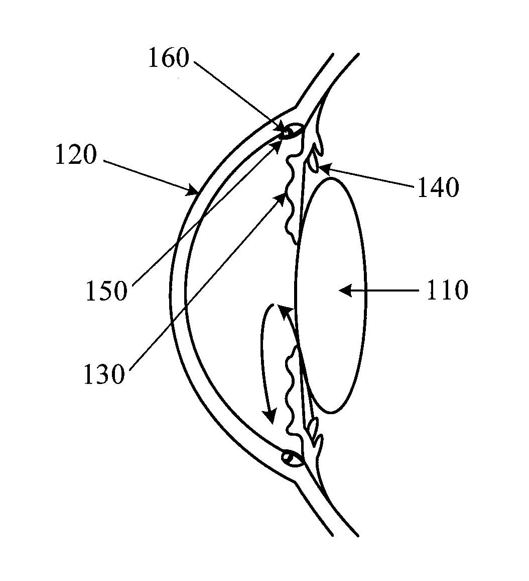
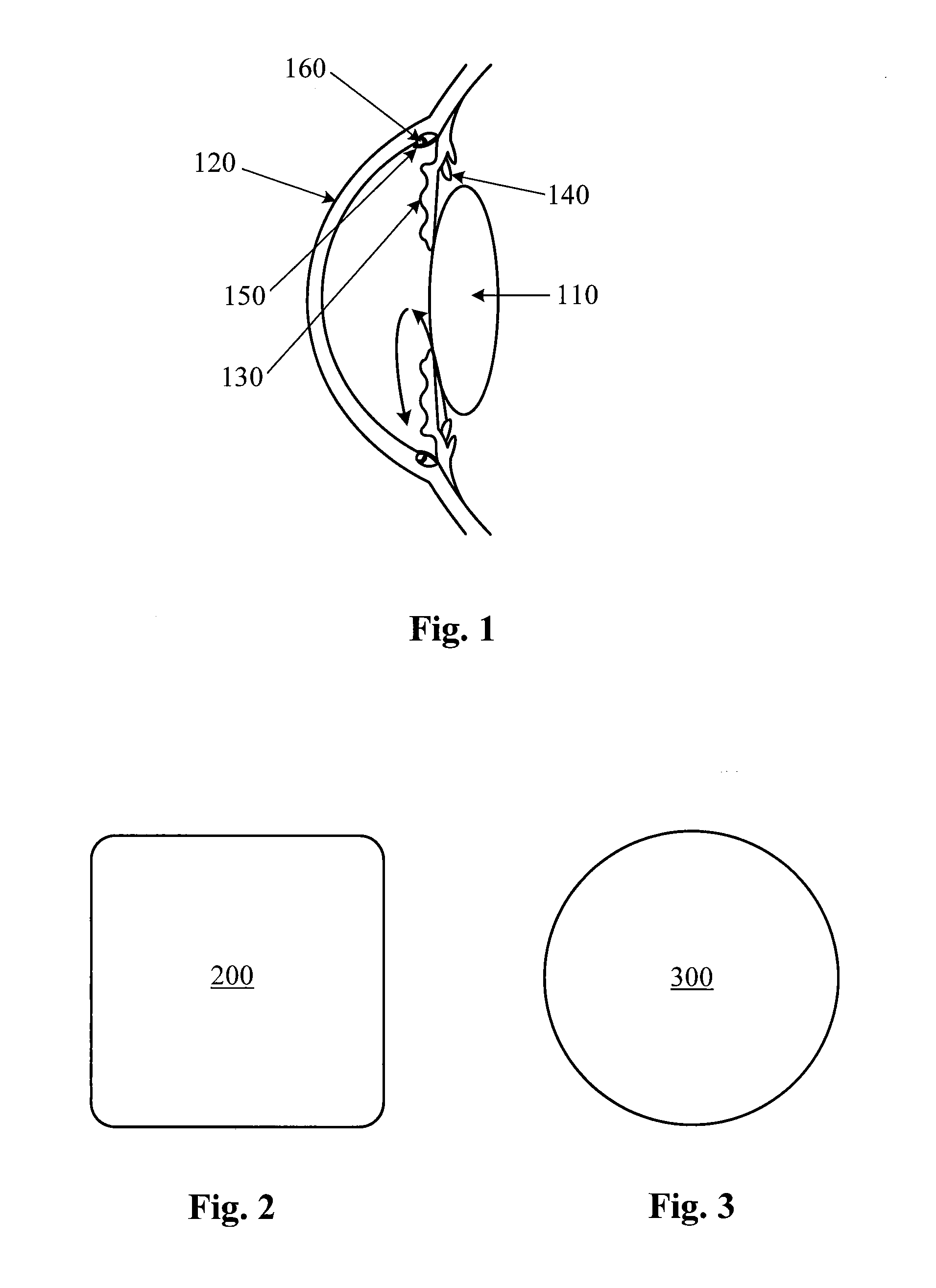
[0021]FIGS. 2 and 3 are top views of two exemplary implantable power systems according to the principles of the present invention. In FIG. 2, the implantable power system 200 has a generally square or rectangular shape with rounded corners. In FIG. 3, the implantable power system 300 has a generally circular or disc shape.

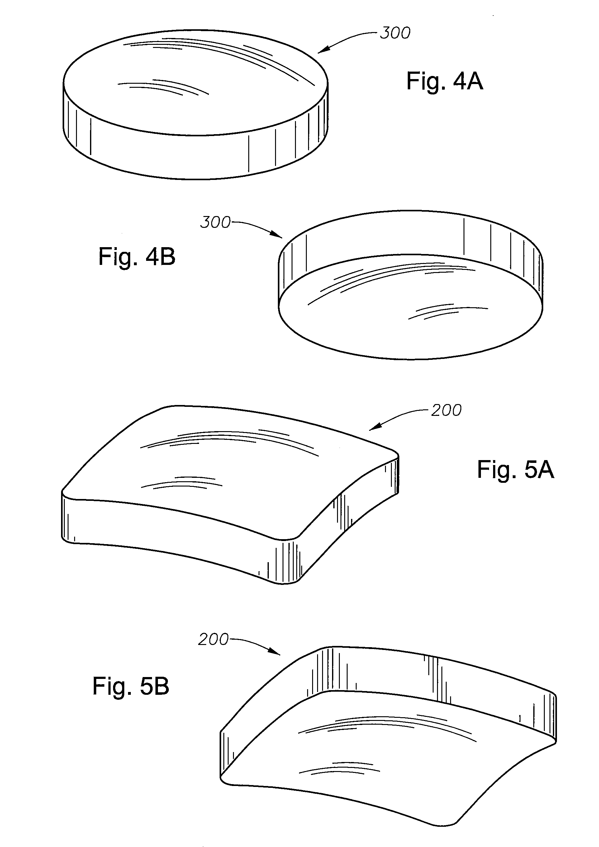
[0022]FIGS. 4A, 4B, 5A and 5B are perspective views of the implantable power supplies (200 and 300) of FIGS. 2 and 3. In FIGS. 4 and 5, the implantable power supplies 200 and 300 are curved so as to fit the curvature of the human eye.

[0023]Implantable power system 200 has dimensions of about 12 millimeters by 12 millimeters wide by 1.5 millimeters thick. In other embodiments of the present invention, the di...


PUM


Abstract

An implantable ophthalmic power system includes a power source and an enclosure. The enclosure surrounds the power source. The enclosure is configured to be implanted under the conjunctiva of the eye.

Description

BACKGROUND OF THE INVENTION[0001]The present invention relates to a power system that is implantable in the eye.[0002]Glaucoma, a group of eye diseases affecting the retina and optic nerve, is one of the leading causes of blindness worldwide. Glaucoma results when the intraocular pressure (IOP) increases to pressures above normal for prolonged periods of time. IOP can increase due to an imbalance of the production of aqueous humor and the drainage of the aqueous humor. Left untreated, an elevated IOP causes irreversible damage the optic nerve and retinal fibers resulting in a progressive, permanent loss of vision.[0003]The eye's ciliary body epithelium constantly produces aqueous humor, the clear fluid that fills the anterior chamber of the eye (the space between the cornea and iris). The aqueous humor flows out of the anterior chamber through the uveoscleral pathways, a complex drainage system. The delicate balance between the production and drainage of aqueous humor determines the...

Claims


Application Information

Patent Timeline
IPC IPC(8): H02J7/00H01G9/00H01L31/00A61F9/00H01M2/00H01L35/30
CPCA61B3/16A61B5/0031A61B2560/0214A61F9/00781H02J7/025H01M2/0222H01M10/0525H01M10/0565H01G9/26H02J7/35Y02E60/10H01M50/109H02J2310/23H02J50/27H02J50/30H02J50/05
Inventor DOS SANTOS, CESARIOJENKINS, DANIELRICKARD, MATTHEW
Owner ALCON RES LTD
Why Eureka
Try Eureka