
Method and Device for Dynamically Shifting a Light Beam with Regard to an Optic Focussing the Light Beam

a technology of dynamic shifting and light beam, applied in the field of raster light microscopy, can solve the problems of not being mechanically accessible, unable to achieve the effect of reducing the cost of operation, and allowing for a comparatively low scanning velocity and correspondingly small frame rate, and achieves the effect of high practical or constructional effor

Active Publication Date: 2011-10-13
DEUTES KREBSFORSCHUNGSZENT STIFTUNG DES OFFENTLICHEN RECHTS
View PDF3 Cites 26 Cited by
  • Summary
  • Abstract
  • Description
  • Claims
  • Application Information

AI Technical Summary

Benefits of technology

The present invention provides an apparatus for dynamically shifting a light beam with regard to an optic, which focuses the light beam and which comprises an optical axis and a pupil. The apparatus includes beam deflectors that deflect the light beam in two different directions with regard to the optical axis of the optic. Each beam deflector deflects the light beam in one direction by a deflection angle that is dynamically variable by a controller. The controller predetermines the deflection angles of all beam deflectors for each point of the two-dimensional scanning range in such a way that the light beam, in scanning the whole two-dimensional scanning range, always runs through a same point of the pupil of the focussing optic. The apparatus can be used in a raster light microscope and can also include a stimulation light source for stimulating an object being scanned. The technical effects of the invention include faster scanning velocities, improved image quality, and reduced aberrations.

Problems solved by technology

Due to mechanical inertia, an object scanner, however, only allows for a comparatively low scanning velocity and correspondingly small frame rates.
In microscope objectives of higher magnification, however, the pupil is located within the objective itself, and it is thus not mechanically accessible.
If the beam pivot point is not exactly in the pupil of the focussing optic, the image brightness strongly drops towards the boundary of the scanning range, which is not acceptable.
The mechanical embodiment of this known raster scanner, however, does not allow for high scanning velocities, and the scanning precision is also limited.
In this way, however, the optical setup becomes complex and has negative effects on the optical transmission.
If one of two separate rotating mirrors, which are rotatable about orthogonal pivot axes, or if even both of them are not arranged in but only close to a single image of the pupil of the focussing optic, this results in a geometric distortion and aberrations besides a varying image brightness over the scanning range.

Method used


Image

  • Method and Device for Dynamically Shifting a Light Beam with Regard to an Optic Focussing the Light Beam
  • Method and Device for Dynamically Shifting a Light Beam with Regard to an Optic Focussing the Light Beam
  • Method and Device for Dynamically Shifting a Light Beam with Regard to an Optic Focussing the Light Beam

Examples


Embodiment Construction

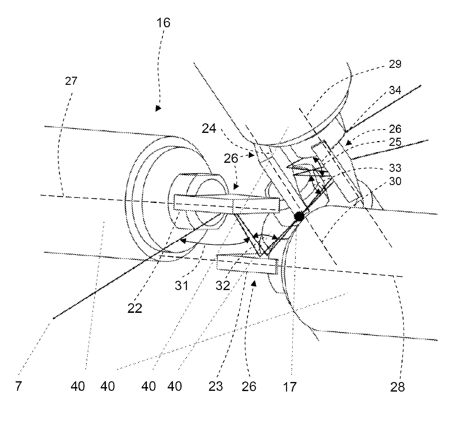
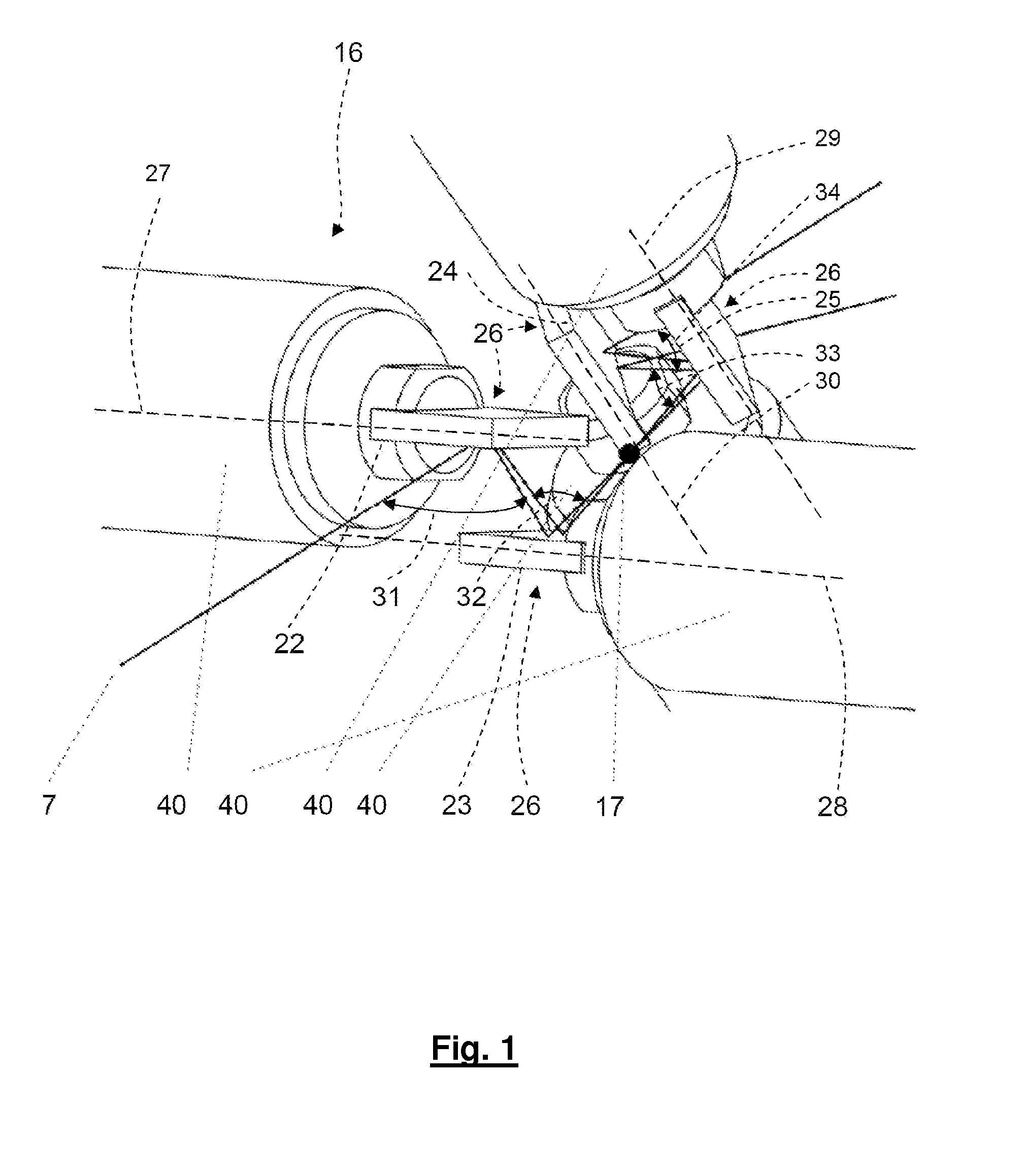
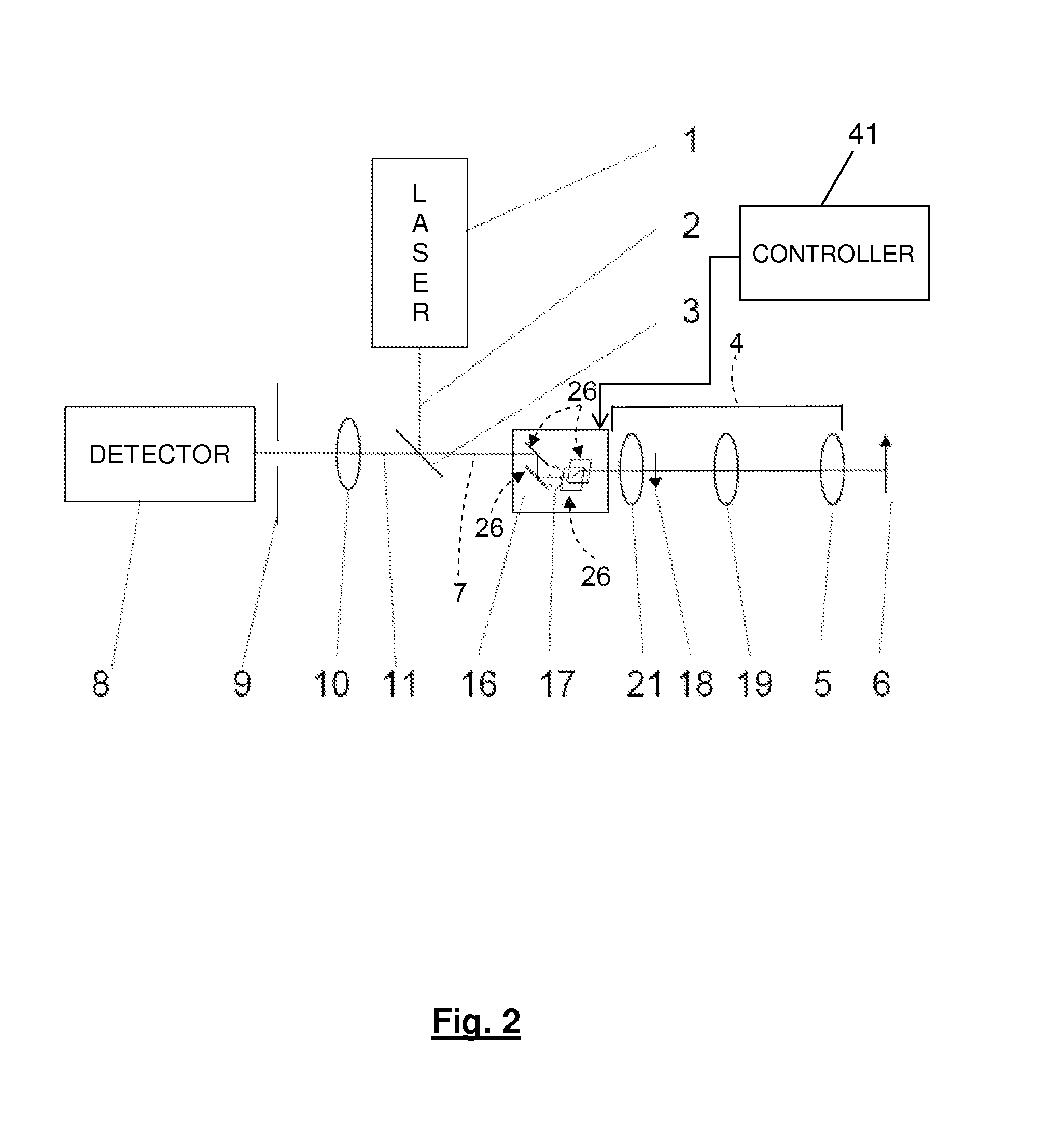
[0027]In the apparatus according to the present invention, at least two and also preferably two beam deflectors are connected in series per direction in which the light beam shall be deflected with regard to the optical axis of the focussing optic to shift it in this direction within the scanning range. The two beam deflectors deflect the beam of light in the same plane but at two points following each other, each by one deflection angle. These two deflection angles are dynamically variable independently on each other. Due to the combination of the independent dynamic variability of the two deflection angles, both the beam position of the light beam in the respective direction within the pupil of the focussing optic and the angle of the light beam with regard to the optical axis of the focussing optic and thus the position of the focussing light beam in the scanning range can be adjusted individually. This particularly means that the beam position in the pupil can be held constant i...


PUM


Abstract

For dynamically shifting a light beam (7) with regard to an optic focussing the light beam to scan an object in a two-dimensional scanning range with the focussed light beam, at least two beam deflectors (26) are connected in series per each direction in which the light beam is to be deflected with regard to the optical axis of the focussing optic. The two beam deflectors deflect the light beam by two deflection angles (31, 32 and 33, 34, respectively) which are dynamically variable independently on each other. The deflection angles (31 to 34) of all beam deflectors (26) are predetermined for each point of the scanning range (35) in such a way that the light beam (7), in scanning the whole two-dimensional scanning range, always runs through the pupil of the optic (4) at essentially the same point.

Description

CROSS REFERENCE TO RELATED APPLICATIONS[0001]This application is a continuation in part to International Application PCT / EP2009 / 067269entitled “Verfahren und Vorrichtung zur dynamischen Verlagerung eines Lichtstrahls gegenüber einer den Lichtstrahl fokussierenden Optik” with an International Filing Date of Dec. 16, 2009 and claiming priority to European Patent Application No. 08172450.2 also entitled “Verfahren und Vorrichtung zur dynamischen Verlagerung eines Lichtstrahls gegenüber einer den Lichtstrahl fokussierenden Optik”, filed on Dec. 19, 2008, now abandoned.FIELD OF THE INVENTION[0002]The invention relates to an apparatus for dynamically shifting a light beam with regard to an optic focussing the light beam. Further the invention relates to a corresponding method of dynamically shifting a light beam with regard to an optic focussing the light beam.[0003]The invention particularly relates to the field of raster light microscopy in which an object is sampled with a focussed lig...

Claims


Application Information

Patent Timeline
Patent Type & Authority Applications(United States)
IPC IPC(8): G02B26/10G02B21/06
CPCG02B26/101G02B21/0048
Inventor ENGELHARDT, JOHANN
Owner DEUTES KREBSFORSCHUNGSZENT STIFTUNG DES OFFENTLICHEN RECHTS
Learn More