Light emitting device creating decorative light effects in a luminaire

a technology of light emitting device and luminaire, which is applied in the direction of semiconductor devices for light sources, lighting and heating apparatus, instruments, etc., can solve the problems of short life span and potential danger of burning objects, and achieve the effect of pleasing and decorative lighting environmen

Inactive Publication Date: 2011-10-13
KONINKLIJKE PHILIPS ELECTRONICS NV
View PDF8 Cites 32 Cited by
  • Summary
  • Abstract
  • Description
  • Claims
  • Application Information

AI Technical Summary

Benefits of technology

[0013]One object of the present invention is to fulfil the above mentioned need and to provide a light emitting de...

Problems solved by technology

Such radial distribution of light is desired, but incandescent light sources suffer from disadvantages such as short life span and potential danger of burning objects that come into contact with the glass bulb.
Howev...

Method used


Image

  • Light emitting device creating decorative light effects in a luminaire
  • Light emitting device creating decorative light effects in a luminaire
  • Light emitting device creating decorative light effects in a luminaire

Examples


Embodiment Construction

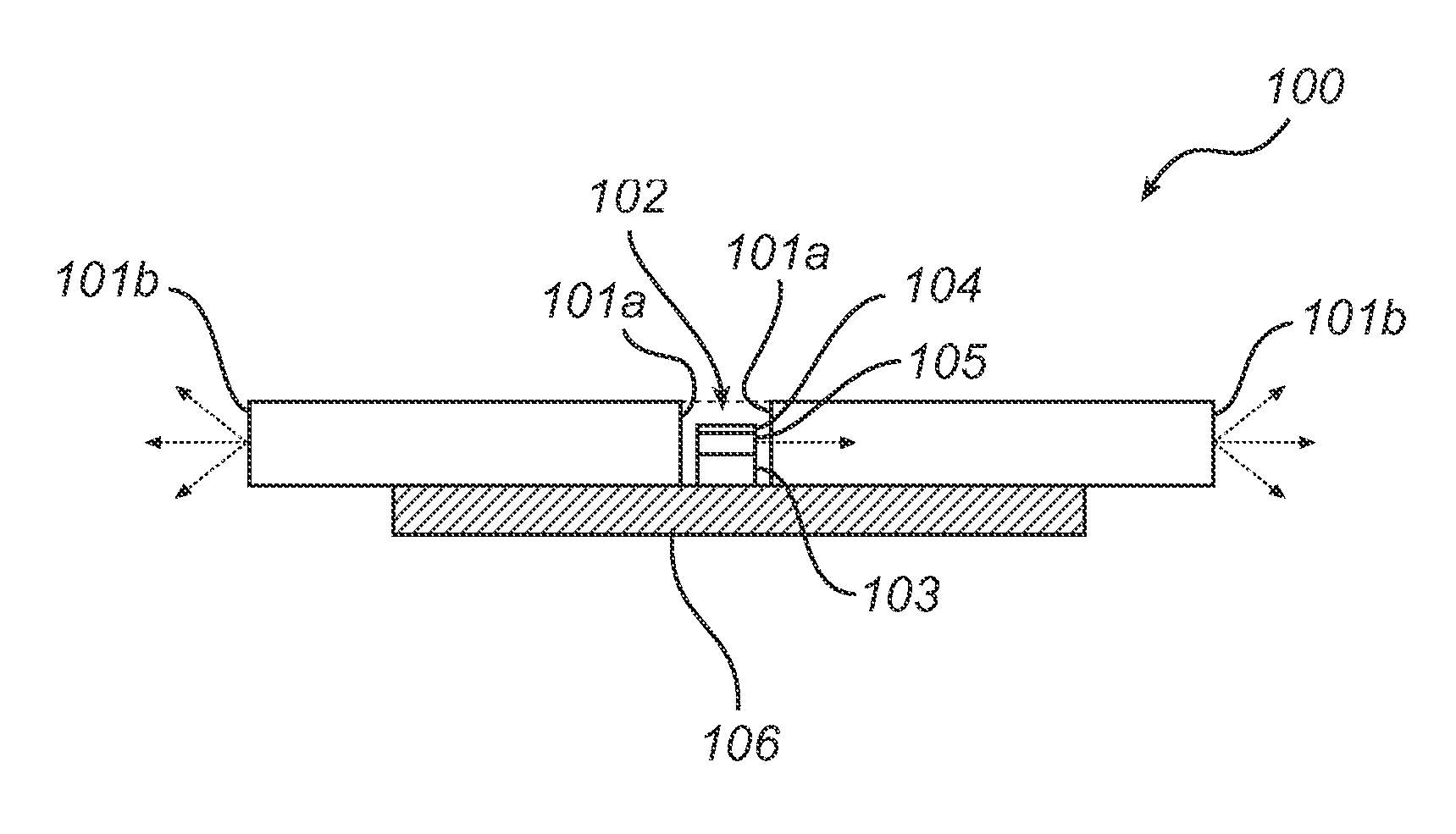
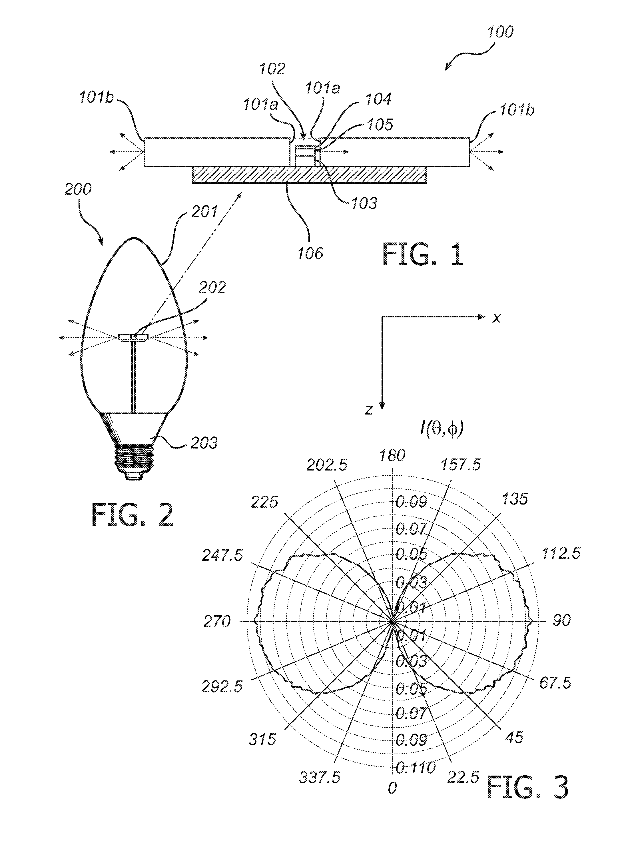
[0045]One embodiment of a light emitting device 100 according to the present invention is illustrated in FIG. 1.

[0046]The device 100 comprises at least one side emitting light source 102 comprising at least one light emitting diode 103 and a reflective layer 104 arranged spaced apart from the LED(s) 103.

[0047]Furthermore, the device comprises a light guide plate 101 which has at least one light input area 101a and at least one light output area 101b. The light guide plate 101 is arranged to extend in a direction generally transverse to the longitudinal axis of the light guide plate 101.

[0048]The light guide plate 101 comprises a depression, wherein the side emitting light source 102 is arranged; said depression forming said light input area 101a.

[0049]Light emitted by the LED(s) 103 is incident on the reflective layer 104, and, independent on the angle of incidence, it will be reflected. The reflective layer 104 is typically essentially opaque such that substantially no light will ...


PUM


Abstract

The present invention relates to a light emitting device (100) comprising a side emitting light source (102) and a light guide plate (101) having at least one light input area (101a) and at least one light output area (101b). Such a device (100) may be used for replacing an incandescent light source or arranged to create various decorative light sparkling effects.
A wide light intensity distribution matching that of an incandescent light source may be achieved.

Description

FIELD OF THE INVENTION [0001]The present invention relates to a light emitting device comprising a side emitting light source and a light guide plate having at least one light input area and at least one light output area; the light guide plate being arranged to extend in a direction generally transverse to the longitudinal axis of the light guide plate.BACKGROUND OF THE INVENTION [0002]For many applications it is desired to create an appealing and pleasing lighting environment, e.g. in a professional or a home setting. For example, chandeliers exhibit light effects, which are considered to be highly decorative.[0003]Chandeliers and other types of luminaires typically utilize conventional incandescent light sources to achieve a pleasant and decorative lighting.[0004]Incandescent light sources typically convert an electrical current to light by applying a current to a filament, which causes the filament to glow. The filament is generally suspended near the center of a glass bulb, the...

Claims


Application Information

Patent Timeline
IPC IPC(8): F21V8/00
CPCF21K9/135F21K9/52G02B6/0073F21Y2101/02G02B6/0021F21V3/00F21K9/232F21K9/61F21Y2115/10G02B6/0001F21W2121/00
Inventor BOONEKAMP, ERIK
Owner KONINKLIJKE PHILIPS ELECTRONICS NV
Why Eureka
Try Eureka