Dual Jet System

a dual-jet system and jet pump technology, applied in the direction of jet pumps, charge feed systems, non-positive displacement pumps, etc., can solve the problems of engine hesitation and stop phenomenon of vehicles, fuel is not smoothly filled in the reservoir,

Inactive Publication Date: 2011-10-13
COAVIS
View PDF9 Cites 8 Cited by
  • Summary
  • Abstract
  • Description
  • Claims
  • Application Information

AI Technical Summary

Benefits of technology

An embodiment of the present is directed to provide a fuel pump module capable of preventing a phenomenon that fuel is not smoothly filled in a reservoir due to an orifice action of a jet pump by inclining fuel to one side that is caused by an inclination of a fuel tank when a vehicle travels a steep slope section.
Another embodiment of the present disclosure is directed to provide a fuel pump module capable of increasing fuel supply efficiency of a vehicle by preventing engine hesitation and stop phenomena of a vehicle caused by insufficiently supplying fuel to an engine since fuel is not previously filled in a reservoir.
In one general aspect, there is provided a fuel pump module 1000 mounted in a fuel tank of a vehicle and supplying a predetermined amount of fuel filled therein to an engine, wherein a dual jet system 400 mounted on a bottom end of a reservoir 310 of the fuel pump module 1000 includes: a main jet pump housing 510 interconnected with at least one first jet orifice 520 and a cylindrical check valve sealing part 530 by a hollow communicating tube 550, at least one first jet orifice 520 jetting the fuel into the reservoir 310 formed at one side of the dual jet system 400 so as to be protruded upward, the cylindrical hollow check valve sealing part 530 formed to be protruded upward while being adjacent to the first jet orifice 520 so that an anti siphon check valve assembly 580 preventing a siphon phenomenon and a reflow of fuel caused at the time of supplying the fuel to the reservoir 310 is inserted into the cylindrical check valve sealing part 530; and a sub-jet pump housing 610 provided with a second jet orifice 620 formed to be protruded upward in order to jet the fuel into the reservoir 310, wherein the bottom side of the reservoir 310 is provided with a coupling groove 800 corresponding to the top side of the dual jet system 400 so that the top surface of the dual jet system 400 may be inserted into the bottom side of the reservoir 310 to be coupled with each other.

Problems solved by technology

However, a case in which the fuel is not smoothly filled in the reservoir 31 through the jet pump 40 under adverse conditions such as when a vehicle stops on a steep slope in a low fuel state or when a vehicle is sharply turned.
Therefore, the engine hesitation and stop phenomena of the vehicle occur due to the fuel insufficiently supplied to the engine.

Method used


Image

  • Dual Jet System
  • Dual Jet System
  • Dual Jet System

Examples


Embodiment Construction

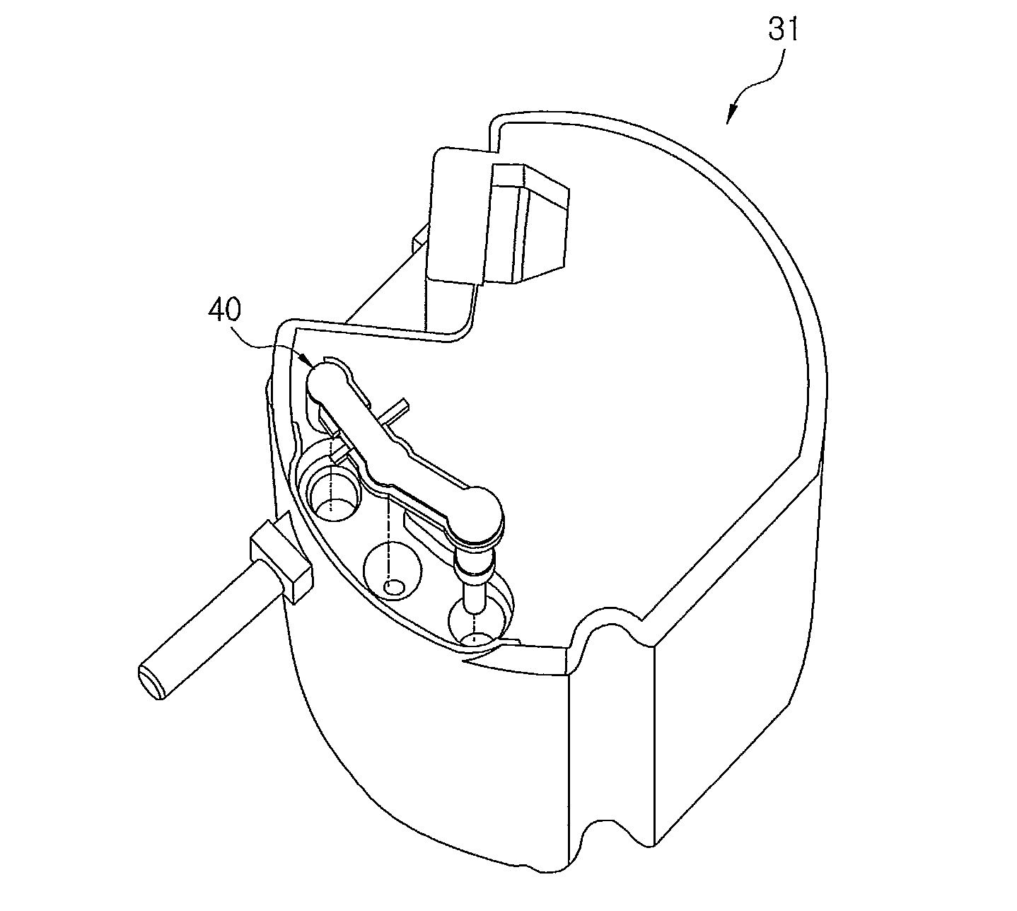
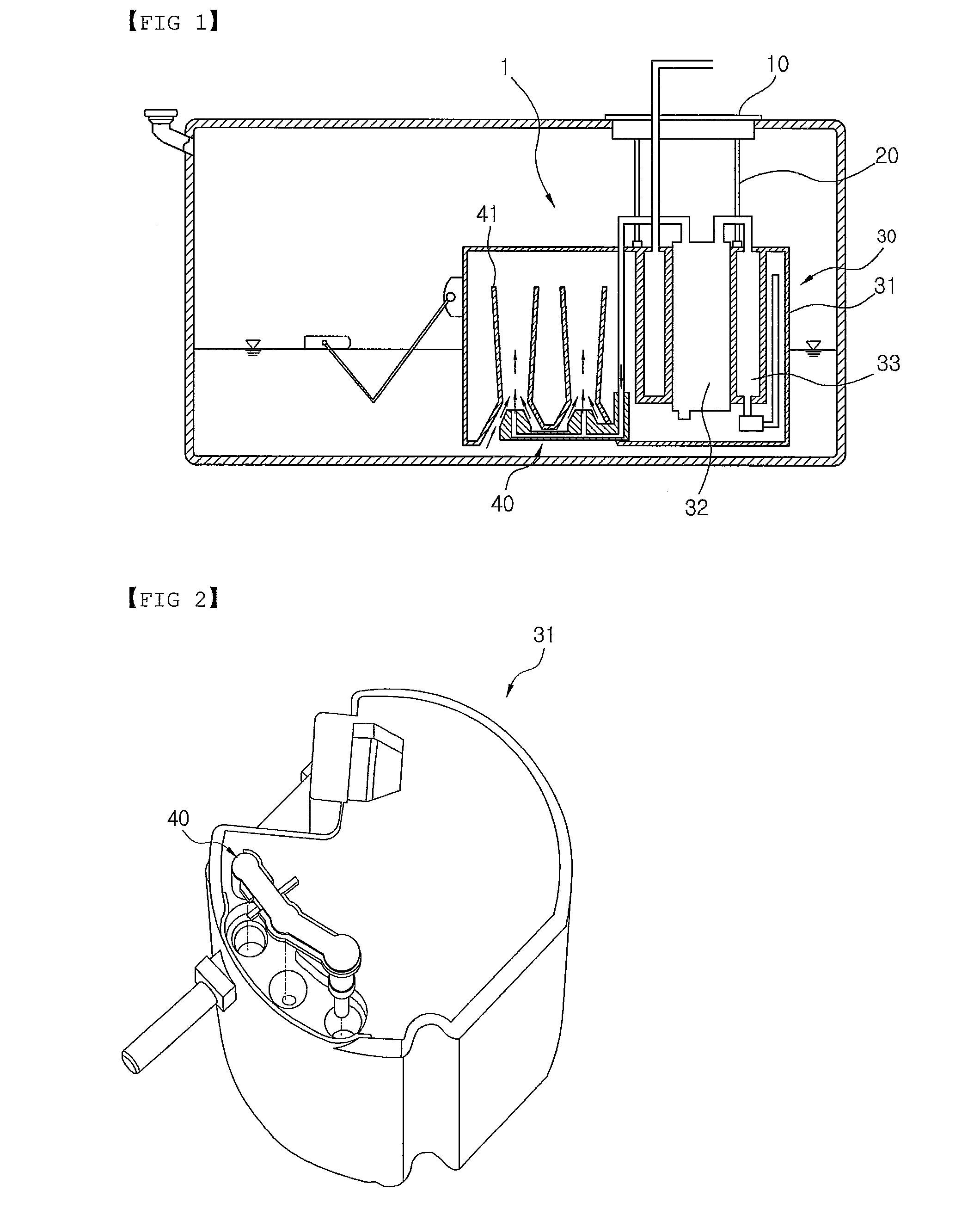
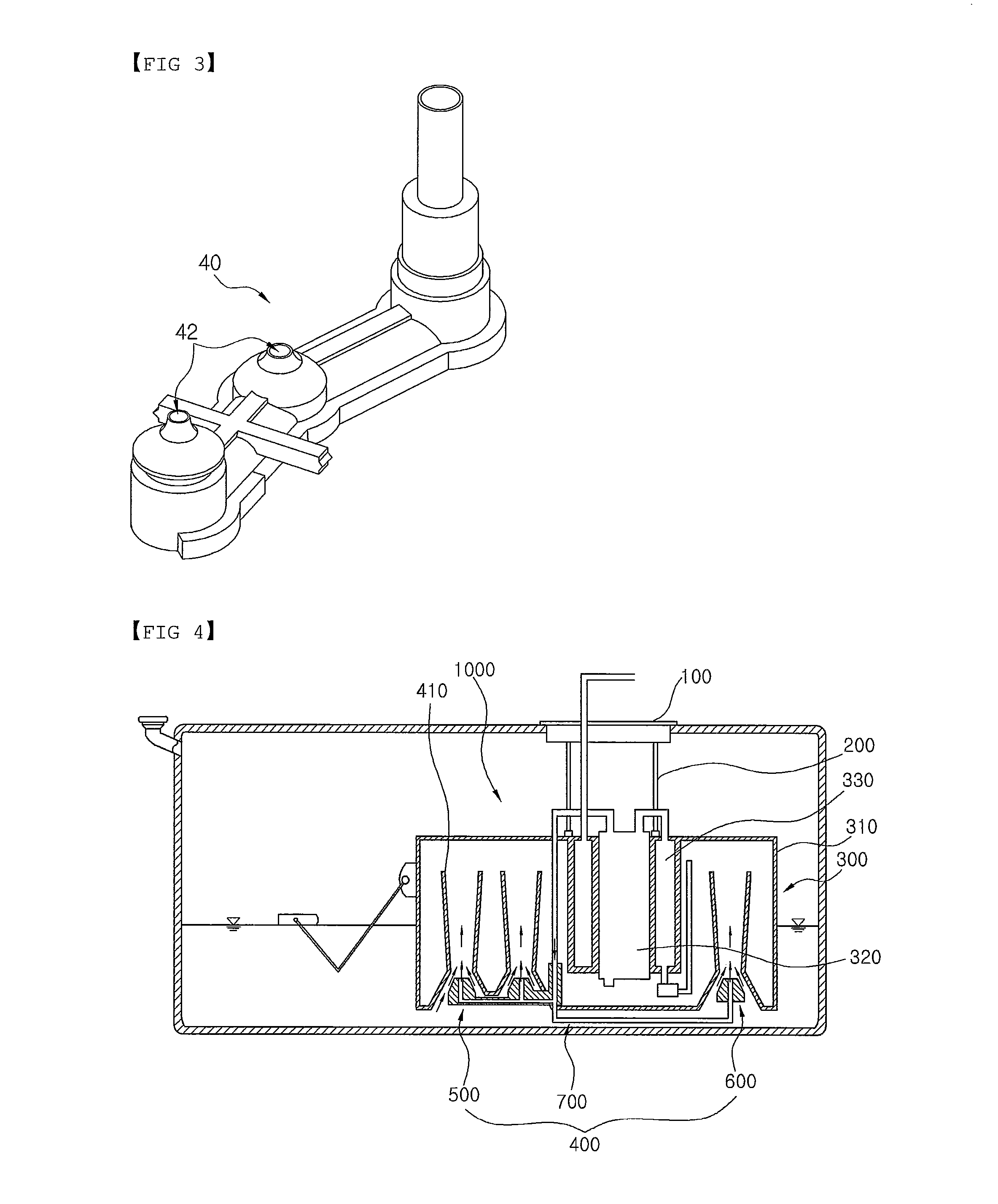
1000: FUEL PUMP MODULE 100: FLANGE ASSEMBLY 200: GUIDE ROD 300: RESERVOIR ASSEMBLY 310: RESERVOIR320: FUEL PUMP 330: INTANK FILTER 400: DUAL JET SYSTEM 410: GUIDE TUBE 500: MAIN JET PUMP 510: MAIN JET PUMP HOUSING520: FIRST JETORIFICE 530: CHECK VALVE SEALING PART540: OUTLET PIPE 550: COMMUNICATING TUBE560: FIRST GAPFORMING PART 570: SECOND GAP FORMING PART571: PROTRUSIONPART 580: ANTI SIPHON CHECK VALVE ASSEMBLY 590: JET PUMP FILTER 600: SUB-JET PUMP 610: SUB-JET PUMP HOUSING620: SECOND JETORIFICE 630: INLET PIPE640: THIRD GAPFORMING PART 700: CONNECTION TUBE 800: COUPLING GROOVE 810: INSERTION GROOVE

DETAILED DESCRIPTION OF EMBODIMENTS

The advantages, features and aspects of the present disclosure will become apparent from the following description of the embodiments with reference to the accompanying drawings, which is set forth hereinafter. The present disclosure may, however, be embodied in different forms and should not be construed as limited to the embodiments set forth herein...


PUM


Abstract

Provided is a dual jet system mounted at a bottom end of a reservoir in a fuel pump module, and more particularly, to a fuel pump module mounted with a dual jet system capable of preventing a phenomenon that fuel is not smoothly filled in a reservoir due to fuel inclined to one side caused by an inclination of a fuel tank when a vehicle travels a steep slope section by mounting two jet pumps at both edges of a bottom end of a reservoir.

Description

CROSS-REFERENCE TO RELATED APPLICATIONSThis application claims priority under 35 U.S.C. §119 to Korean Patent Application No. 10-2010-0032704, filed on Apr. 09, 2010, in the Korean Intellectual Property Office, the disclosure of which is incorporated herein by reference in its entirety.TECHNICAL FIELDThe present disclosure relates to a dual jet system mounted at a bottom end of a reservoir in a fuel pump module, and more particularly, to a fuel pump module mounted with a dual jet system capable of preventing a phenomenon that fuel is not smoothly filled in a reservoir due to fuel inclined to one side caused by an inclination of a fuel tank when a vehicle travels a steep slope section by mounting two jet pumps at both edges of a bottom end of a reservoir.BACKGROUNDGenerally, a fuel supply apparatus of a vehicle is a fuel apparatus of a vehicle driven by being supplied with liquid fuel, like a gasoline engine or a diesel engine. The fuel supply apparatus is an apparatus of supplying f...

Claims


Application Information

Patent Timeline
Patent Type & Authority Applications(United States)
IPC IPC(8): F04F5/00F04F5/46
CPCF02M37/025F04F5/10F02M37/18F02M37/106
Inventor KIM, KYUNGHWANKIM, JEONGSIKKIM, HOIHYUN
Owner COAVIS
Why Eureka
Try Eureka