Eureka AIR delivers breakthrough ideas for toughest innovation challenges, trusted by R&D personnel around the world.

Method for producing a pattern on a continuous strip

Inactive Publication Date: 2011-10-13
VOITH PATENT GMBH
View PDF5 Cites 5 Cited by
  • Summary
  • Abstract
  • Description
  • Claims
  • Application Information

AI Technical Summary

Benefits of technology

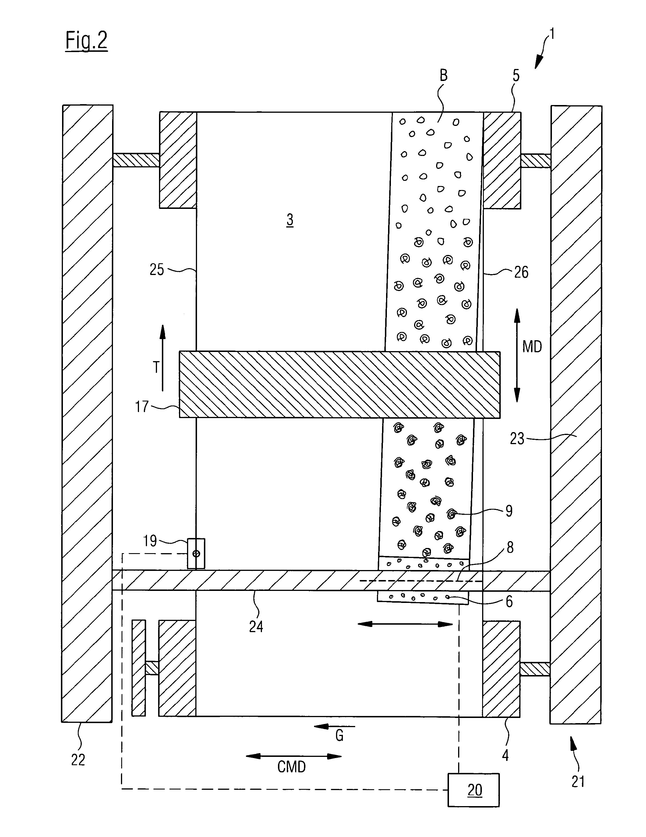
[0013]The position of the applicator device is corrected accordingly with each offset or drift of the continuous strip parallel to its transverse orientation. Due to this, a drift of the continuous strip is no longer recognizable in the pattern which is applied onto the continuous strip, since the position of the applicator device is corrected immediately and, accordingly, following measurement of the drift or offset parallel to the transverse orientation of the continuous strip. This permits clear improvement of the control over the polymer application parallel to the transverse orientation of the continuous strip, resulting in a clear reduction in the offset of pattern elements in the transverse direction of the continuous strip.
[0032]This arrangement of the present invention provides that the rotary screen performs one or several whole rotations around its longitudinal axis on the circumferential surface of the continuous strip during each revolution of the path. This provides that the rotary screen at the end of each revolution of the path is in the precise rotational position in which it was at the beginning of the revolution of the path. This ensures that the elements of the pattern at the beginning of the revolution of the path adjoin the pattern elements at the end of the revolution of the path without offset. This clearly allows an offset of the pattern elements forming the pattern to be further reduced.

Problems solved by technology

The problem with this is that the adjacently located pattern segments are often considerably offset relative to each other.

Method used


Image

  • Method for producing a pattern on a continuous strip
  • Method for producing a pattern on a continuous strip
  • Method for producing a pattern on a continuous strip

Examples


first embodiment

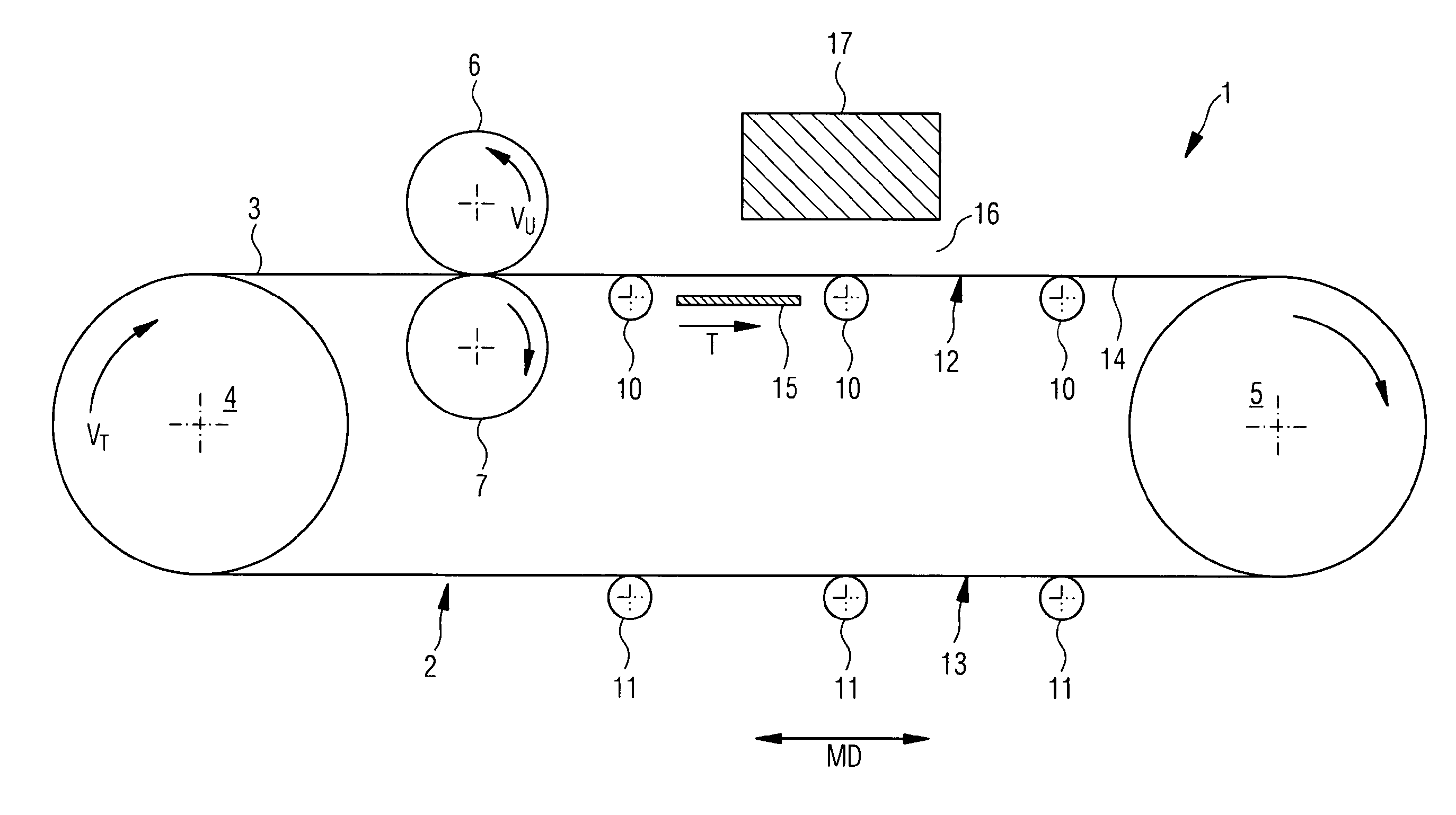
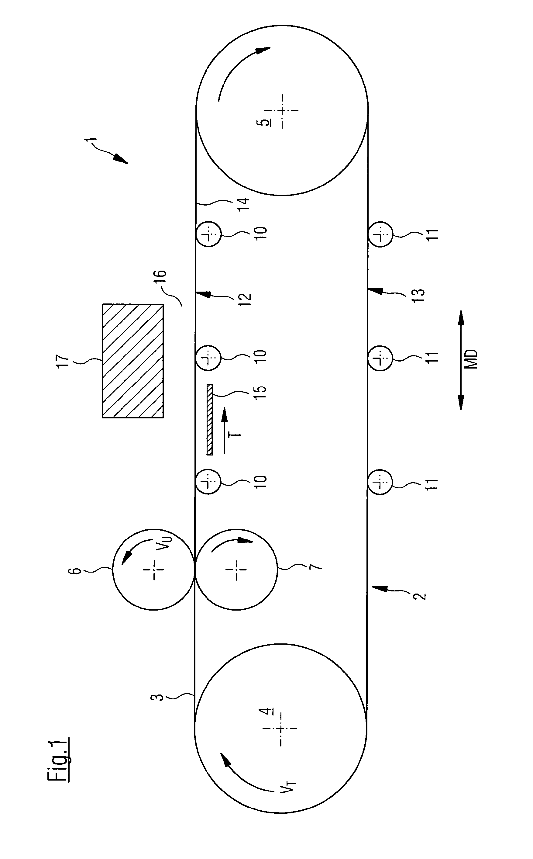
[0107]Referring now to FIG. 3, there is shown the method of the present invention. Here, rotary screen 6 rolls on circumferential surface 3 in an uninterrupted helix type path B. Path B is formed by a plurality of adjoining path revolutions, whereby in this example, revolutions of paths BU1 and BU2 are indicated. Each revolution of path BU1, BU2 is limited in its length by beginning A and end E. Revolution of path BU1, for example, is limited in its length by beginning A1 and end E1. As can be seen in the illustration in FIG. 3, ends E1, E2 and beginnings A1, A2 of all revolutions of paths BU1, BU2 are located on common straight line 18 which, together with longitudinal direction MD of continuous strip 2 encompasses angle α≠90°. In this case, beginning A1, A2 and end E1, E2 of all revolutions of paths BU1, BU2 are arranged on common straight line 18 extending diagonally to the longitudinal and transverse orientation of continuous strip 2. Beginning A1, A2 and end E1, E2 of each path...

second embodiment

[0114]Referring now to FIG. 4, there is shown the method of the present invention. Here, rotary screen 6 rolls on circumferential surface 3 in uninterrupted helix-type path B.

[0115]In this case too, basic movement G and transport movement T complement each other such that rotary screen 6 rolls on circumferential surface 3 of continuous strip 2 in an uninterrupted helix type path. Furthermore, also in this case, rotary screen 6 moves at basic movement G continuously parallel to cross direction CMD of continuous strip 2.

[0116]Path B is formed by a plurality of adjoining revolutions of paths BU, whereby in this example revolutions of paths BU1′ and BU2′ are indicated. Each revolution of path BU1′, BU2′ is limited in its length by beginning A and end E. Revolution of path BU1′, for example, is limited in its length by beginning A1′ and end E1′. As can be seen in the illustration in FIG. 4, ends E1′, E2′ and beginnings A1′, A2′ of all revolutions of paths are located on common straight l...


PUM


Abstract

A method for producing a polymer topographic pattern on a continuous strip which has a longitudinal orientation and transverse orientation perpendicular thereto. The pattern is applied to an area of the continuous strip to be imprinted by means of an application device moving in relation to the strip in a basic movement which is parallel to the transverse orientation of the strip to produce the pattern. During production of the pattern, the position of the continuous strip parallel to its transverse orientation, relative to a stationary reference position, is measured and the position of the application device is changed by a correction movement parallel to the transverse orientation of the continuous strip when the position of the continuous strip parallel to its transverse orientation is changed, the correction movement being superimposed to the basic movement.

Description

CROSS REFERENCE TO RELATED APPLICATIONS[0001]This is a continuation of PCT application No. PCT / EP2009 / 059803, entitled “METHOD FOR PRODUCING A PATTERN ON A CONTINUOUS STRIP”, filed Jul. 29, 2009, which is incorporated herein by reference.BACKGROUND OF THE INVENTION[0002]1. Field of the Invention[0003]The present invention relates to a method for producing a polymer topographic pattern on a continuous strip.[0004]2. Description of the Related Art[0005]Especially in the production of tissue paper, screens with decorative topographic patterns are used. Tissue paper thereby produced is embossed with the topographic pattern of the screens.[0006]Various methods of applying the topographic pattern onto a continuous strip are known in the current state of the art. It is, for example, conceivable to apply the topographic pattern by means of a rotary screen printing process or extrusion die process.[0007]Current paper machine clothing often has widths of 10 meters or more. In contrast, printi...

Claims


Application Information

Patent Timeline
IPC IPC(8): B05D5/00
CPCD21F11/006D21F1/0036
Inventor ALLUM, ANDREWJEFFREY, JOHNPONTON, DAVID S.MORTON, ANTONYDOUGLAS, STEPHEN
Owner VOITH PATENT GMBH
Why Eureka
Eureka Blog
Learn More