Communication device and method thereof

a communication device and power control technology, applied in power management, wireless commuication services, electrical equipment, etc., can solve the problem of increasing the complexity of transmitting power control

Inactive Publication Date: 2011-10-13
HTC CORP
View PDF0 Cites 180 Cited by
  • Summary
  • Abstract
  • Description
  • Claims
  • Application Information

AI Technical Summary

Benefits of technology

[0014]Another embodiment of a method for a communication device is revealed, comprising receiving, by the telecommunication device, a plurality of downlink transmission signals on a plurality of downlink carriers, in response to the downlink transmission signals, transmitting, by the telecommunication device, at least one uplink control signal comprising a Channel Quality Indicator (CQI), a Scheduling Request (SR), or ACK / NACK according to at least one PUCCH resource, wherein the at least one PUCCH resource is determined or used according to at least one configuration parameter specific to the telecommunication device, at least one carrier offset relative to at least one downlink carrier, at least one received PDCCH resource, a bandwidth of the first carrier, at least one PUCCH format type, a cell configuration, an orthogonal hopping sequence, or a cyclic shift pattern.
[0015]Yet another embodiment of a method for a communication device is provided, comprising being configured with at least one uplink carrier and at least one downlink carrier according to a carrier aggregation configuration, transmitting a first PUCCH format comprising a PUCCH format type information and power headroom report for at least one of the at least one uplink carrier, or transmitting a second PUCCH format comprising at least one of at least one ACK / NACK signaling and at least one channel quality indicator in response to at least one downlink transmission on at least one of the at least one downlink carrier.

Problems solved by technology

The employment of the MIMO scheme increases the complexity of transmit power control.

Method used


Image

  • Communication device and method thereof
  • Communication device and method thereof
  • Communication device and method thereof

Examples


Embodiment Construction

[0025]The following description is of the best-contemplated mode of carrying out the invention. This description is made for the purpose of illustrating the general principles of the invention and should not be taken in a limiting sense. The scope of the invention is best determined by reference to the appended claims. The 3GPP specifications are used to teach the spirit of the invention, and the invention is not limited thereto.

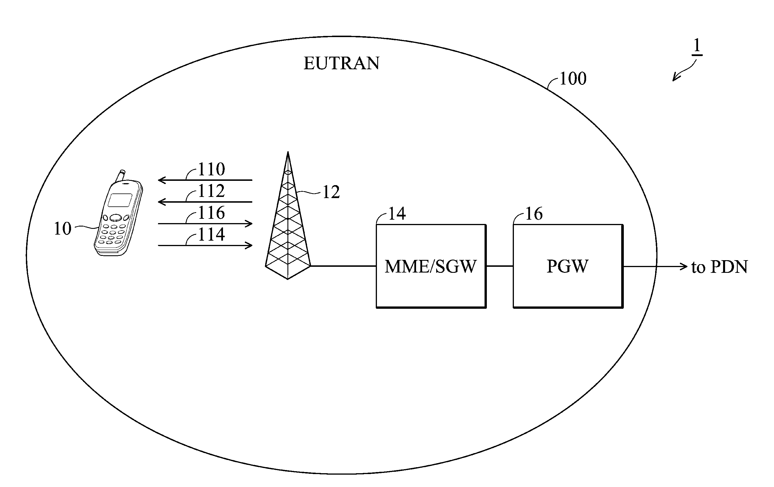
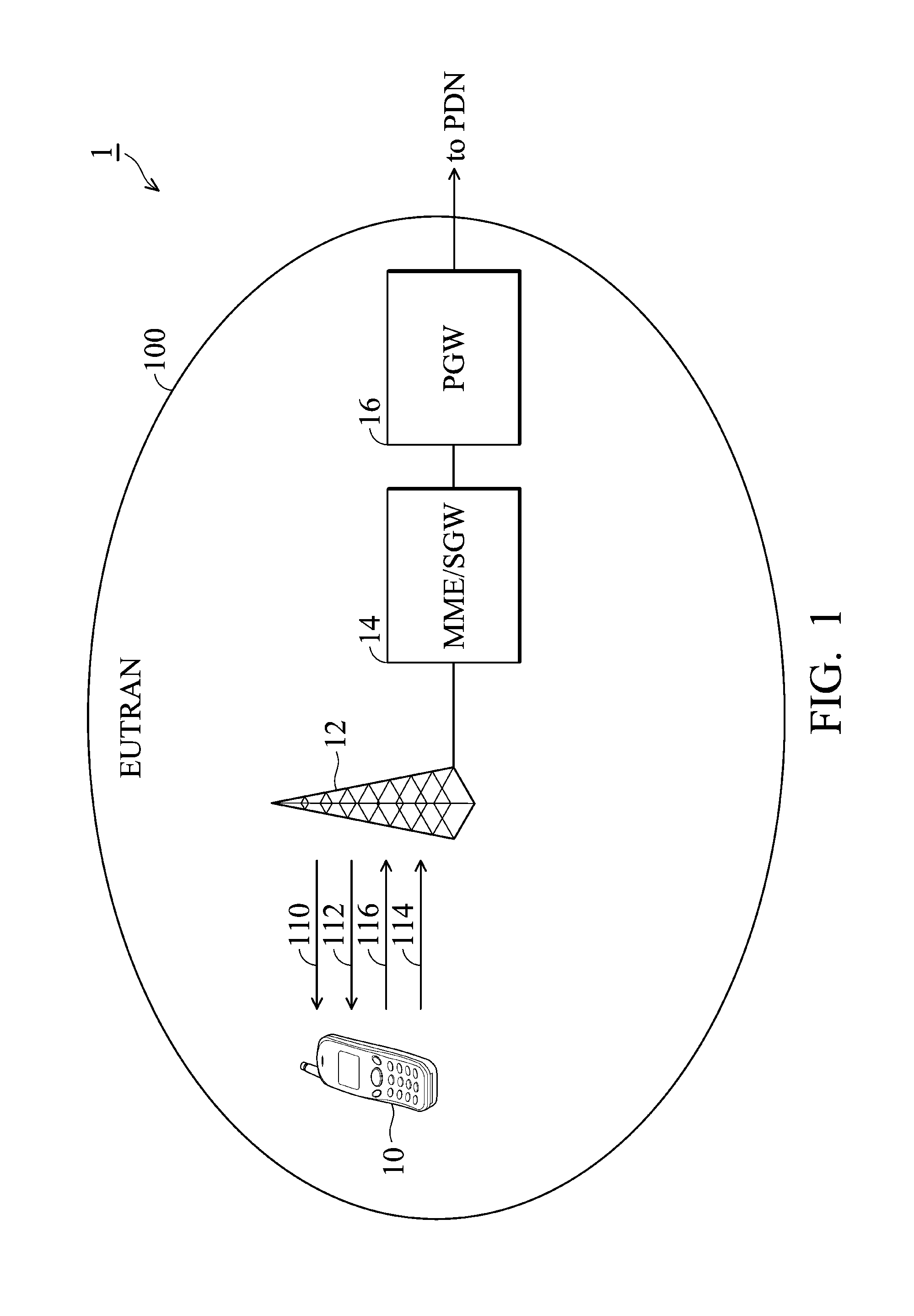
[0026]FIG. 1 depicts a system diagram of a Long Term Evolution (LTE) and / or LTE-Advanced (LTE-A) wireless communication system 1, comprising a UE 10, an evolved Node-B (eNB) 12, a Mobility Management Entity / Serving Gateway (MME / SGW) 14, and a Public Data Network (PDN) gateway (PGW) 16. The UE 10 is coupled to the eNB 12, and then to the MME / SGW 14, and then to the PGW 16. Although a single UE 10 and eNB 12 are shown in FIG. 1, it should be apparent that any number and any combination of wireless and wired UE 10 and eNB 12 devices may be incorporated in the L...


PUM


Abstract

Methods for a communication device. The method comprises being configured with at least one uplink carrier and at least one downlink carrier according to a carrier aggregation configuration, receiving at least one control signal at least one downlink control channel on the at least one downlink carrier, determining at least one control format of the at least one control signal for at least one uplink or at least one downlink transmission or for at least one control signaling carried on the same or different at least one uplink carrier or the at least one downlink carrier, and performing at least one of the at least one uplink and the at least one downlink transmission or at least one control signaling on the same or different at least one uplink carrier or the at least one downlink carrier according to the at least one control format of the at least one control signal, wherein the at least one of at least one uplink and the at least one downlink transmission or the at least one control signaling use a same or different transmission modes on the same or different at least one uplink carrier or the at least one downlink carrier.

Description

CROSS REFERENCE TO RELATED APPLICATIONS[0001]This application claims the benefit of U.S. Provisional Application No. 60 / 321,691, filed on 7 Apr. 2010, the entirety of which is incorporated by reference herein.BACKGROUND OF THE INVENTION[0002]1. Field of the Invention[0003]The present invention relates to power control, and in particular relates to a communication device and method thereof for providing power control of the multiple carriers.[0004]2. Description of the Related Art[0005]A Long Term Evolution (LTE) or LTE Advanced (LTE-A) system is an evolved next-generation wireless communication system proposed by the Third Generation Partnership Project (3GPP). A user equipment (UEs) compliant with the LTE / LTE-A system may simultaneously transmit and receive data on one or more component carriers. The LTE-A system provides high-speed low-latency packet-based communications at a data rate of up to 100 Mbps through engagement of carrier aggregation, where up to five 20 MHz component c...

Claims


Application Information

Patent Timeline
Patent Type & Authority Applications(United States)
IPC IPC(8): H04W52/04H04W72/04H04W4/00
CPCH04W52/08H04W52/34H04W52/48H04W52/365
Inventor JEN, YU-CHIH
Owner HTC CORP
Why Eureka
Try Eureka